


Introduction
Engineers made some dismantling and comments on the battery system design and power system of Model S Plaid on the tubing. I would like to sort out this content in two phases. Since the module is not dismantled here, the main information that can be obtained includes: the design idea and electrical design of the overall module structure. As far as I understand this design, the capacity to be improved in the future is 400V+*900A, and the route of high current is taken.
A teardown analysis (Ingineerix) video of the Model S plaid has been placed on Planet of Knowledge.
Design of battery module
This battery system is divided into 5 areas as a whole. From the current design, it may be transitioned from a large module to the degree of bonding with the system as a whole.

The positive and negative electrodes of these 5 large battery blocks are arranged on the two long sides, and are connected in series by busbar welding. The configuration of the batteries in the module is 22S72P, and the entire battery system reaches 110S72P, which actually increases the overall voltage. The voltage is 401V, and the number of cells is 7920 18650 cells according to preliminary calculations. Panasonic has improved the energy density on this cell. The size of the module is still unclear, and it is extended along the width direction, about 1.3-1.4m.
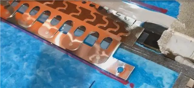
In the busbar design at the edge of the module on this side, it can be said that the design is very interesting: a certain degree of fuse protection, I think this is the key to Tesla’s effective use of Pyro fuse, if only relying on Pyro fuse to compare the functional safety level requirements High, the two-level physical fuse protection of cells and modules is used here, and redundancy is also achieved at different levels.


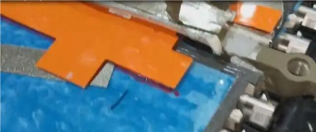
At present, like Model Y’s 4680, Tesla makes the sampling board CMU of BMS into a long strip, and then integrates it in the module. It is also fixed on the endplate through structural parts and glue, and directly passes through the busbar of the bus bar between the cells. The pins are connected to the PCB board, which is almost exactly the same.
Electrical design
In the layout of the entire Pack, the Model S Plaid was designed to be a high-performance model from the beginning, so it needs to be designed in the direction of four-wheel drive, and it has very new features in the electrical design.
It is divided into two parts here:
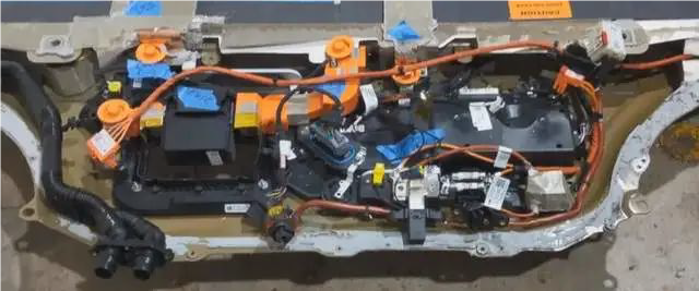
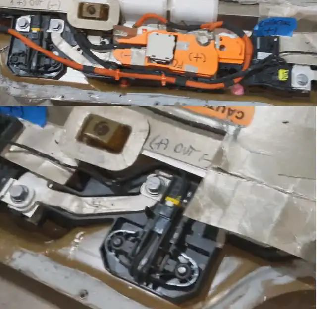
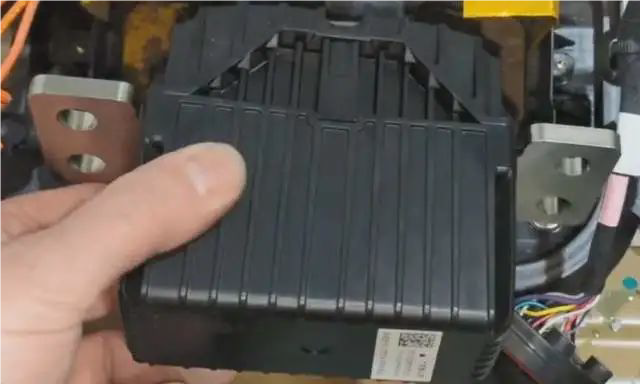
BDU and BMS and fuse: put them on the front, only Pyro fuse has designed the service window as the front BDU;
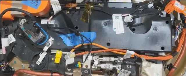
Combination of contactors: main positive, main negative and two twin fast charge contactors are placed at the rear of the battery system, and a maintenance window is designed to be handled from under the seat.
Tesla cleverly uses two huge long busbars to connect the two BDUs.
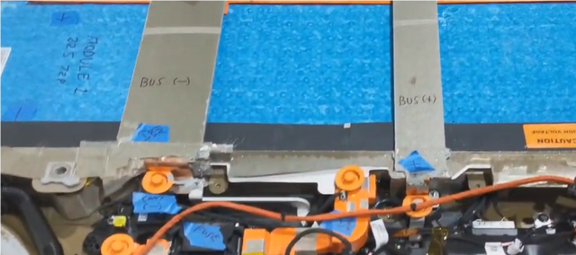
The thing to pay attention to is that more and more car companies have begun to do half-voltage protection, that is, the main fuse is placed in the middle of the connection between the large modules. There is a detailed calculation process for the design and protection of half-voltage. I have carefully I have calculated it, and I will share the calculation process when I have time.
From the specifications of the supply chain feedback, Tesla’s goal is to continuously increase the charging current, and in the future, it wants to increase to 900A or even higher, so throughout the electrical design, the protection devices involved in the charging circuit have been improved. Therefore, this Pyro fuse is larger than the previous one. On the one hand, it is necessary to increase the design of the arc extinguishing area, and to improve some of the previous historical design problems.
Remarks: It is a more effective method to learn the actual principle and experimental information from the device supplier.
Due to the introduction of heat pumps in all Tesla systems, Tesla currently only needs 2 auxiliary fuses, and the whole vehicle only needs to protect the air-conditioning compressor and the PCS circuit in two directions. At present, the battery management system is defined as a component that is unlikely to be damaged. At least from the perspective of the BMS and PCS components, the failure rate should be upside down, so the layout has also been changed.
Conclusion
I think the biggest design feature of this bag is that there are many improvements in electrical design. Sometimes it is a miracle, and you really have to choose good enough electrical components to have a good design. I feel that there are still some design details that have not been worked out yet, and I will sort out the ideas when I have time.
BCT and 120V120A 1ch machine. You can add this machine from Semco.
More Articles:
Lithium-ion Battery Packaging Information for Beginners,
Lithium Battery Protection Board,
Application of Isolation testing Technology,
Action protector in electric vehicle charging system,
History of Lithium Battery Development,
Production problems of lithium batteries,
Formation Process of Lithium Battery,
Principles of Power Battery System Design,
Battery Pole Piece Coating Process,
Point Defects in Pole Piece Coating,