

Liquid cooling plates are typically composed of thin aluminum alloy heat sinks arranged in nested or welded structures. They also have internal channels to guide the flow of the cooling medium and remove heat.
Liquid cooling plates undergo rigorous airtightness testing before leaving the factory to ensure heat dissipation performance and durability. The following article will provide a detailed overview of the airtightness testing process for liquid cooling plates.

Methods for testing the airtightness of liquid-cooled plates
Pressure method: Also known as the pressure reduction method or gas testing method. There are usually several testing methods, such as direct pressure air tightness testing and differential pressure air tightness testing. The testing method is selected according to different product requirements. The air tightness test of the liquid cooling plate of the power battery is usually carried out by the direct pressure testing method.
This method requires injecting gas at a specific pressure into the liquid cooled plate component according to the testing requirements, observing the change in internal pressure of the workpiece by holding the pressure, and then determining whether there is a leak in the liquid-cooled plate component; observe its pressure holding condition, if the pressure holding capacity exceeds the standard, the liquid-cooled plate has good airtight performance.

Soaking method: Also known as water testing, the liquid cooling plate to be tested is immersed in water, and then it is observed whether bubbles are generated . If bubbles are generated, it indicates that the liquid cooling plate has a hole and does not meet the testing standards.
Hydrogen leak detection method: Before testing, prepare a container filled with water and pressurize the water in the container so that the pressure difference before and after the test is between 5 and 10 MPa. Then place the outlet of the liquid cooling plate below the water surface in the pressurized container. If the liquid cooling plate leaks, the hydrogen gas at the outlet will be absorbed by the water. The location of the leak point can be determined by detecting the hydrogen gas in the water with a detection instrument.

Thermal cycling method: This method involves first placing the liquid cooling plate in a low temperature environment, then rapidly heating it to a high-temperature environment , and observing whether the liquid cooling plate is deformed or has leaks. If so, it indicates that the liquid cooling plate has poor airtightness.
Water-cooled plate testing requirements
Test pressure: 200kPa-250kPa; Standard: Test for 30 seconds
Introduction to Airtightness Testing
An airtightness test, also known as a sealing test or waterproof test, is a method to verify the airtightness of a container . It is a tightness test using gas as the pressurized medium, employed to prevent leaks in pressure vessels. An airtightness test can only be performed after a hydraulic test has passed. The testing method may vary depending on the specific device being tested.
In the process of selecting and preparing for testing, some principles need to be mastered. The liquid inside the device should form a closed environment so that the temperature can be changed and the pressure intensity can be changed. This change can be used to effectively judge the airtightness.
Generally, battery manufacturers and vehicle manufacturers require battery packs to meet an IP67 rating or higher, which places high demands on the battery pack’s waterproofing technology. Therefore, an important performance characteristic—battery airtightness— must be considered from the initial design stage of the battery pack to ensure it can pass immersion tests.

Factors affecting the airtightness of battery packs
Carbon steel sheet metal enclosure: Generally, carbon steel sheet metal enclosures are made by stamping parts from sheet metal, then directly assembling them, and finally spot welding them together. During welding, it is crucial to control the welding current to prevent burn-through or missed welds. Secondly, after the enclosure is welded and formed, it needs to be shaped, especially ensuring that the sealing surface of the enclosure is flat and free of burrs. Thirdly, the surface roughness of the paint film on the mounting surfaces of the connectors must be maintained.
Aluminum alloy profile enclosure: The process of “aluminum profile extrusion molding + friction stir welding + cold metal transfer (CMT) repair welding” is currently a common practice. Specific control points are as follows:
First, it is necessary to prevent burn-through, misaligned seams, and missed solder joints in CMT.
Secondly, during friction stir welding, the contact between the cutting tool and the bottom plate of the battery pack generates a large amount of heat, causing deformation of the pack. This results in uneven pressure on the sealing gasket during subsequent assembly, leading to varying compression deformation rates. When a pressure difference occurs between the inside and outside of the battery pack, air leakage can occur. To ensure good welding quality and reduce deformation and welding defects, the recommended parameters for friction stir welding are 1600–1800 r/min and a travel speed of 800–1000 mm/min. Next is CMT repair welding. After friction stir welding is completed, manual welding is generally used for repair. Full welding is applied to areas prone to leaks or poor welds, especially at the junction of the enclosure sealing surface and frame, where the thickness is typically 2mm. Due to the inherent characteristics of aluminum alloy, insufficient welding current leads to inadequate weld depth and incomplete welds; excessive welding current can cause cracking and through-welds in thin areas.

To ensure welding strength, it is often necessary to build up weld at the joint, with a height generally ≤2.5mm. However, the high weld height can create irregular angles and gaps between the weld and the flange face. During assembly, when the cover compresses the gasket, the gasket will be subjected to different compressive stresses, requiring the weld to be ground to form an optimal rounded transition shape. During assembly, the gasket deforms under stress, which can fill the area around the weld, achieving a good sealing effect.

In addition to adjusting the process parameters of friction stir welding, it is also necessary to manufacture high-quality welding fixtures to reduce welding deformation and minimize welding defects.
Aluminum die-cast housing: Aluminum die-cast enclosures can be integrally molded. Key improvements focus on the alloy material to prevent manufacturing defects such as pinholes and inclusions. Furthermore, aluminum die-cast enclosures require high flatness and precision on the sealing strip mounting surface, necessitating precision machining. Aluminum die-cast enclosures are generally suitable for small battery packs. For larger battery packs, welding can be used to compensate. These enclosures generally meet IP67 standards well. However, cast enclosures are limited by molds, process conditions, and inherent quality. For large battery packs, specific considerations regarding lightweight design and process feasibility are necessary.

Sealing gasket: The sealing gasket plays a crucial role in the overall airtightness of the package. The material must be flame-retardant and meet the automotive industry’s standards for prohibited substances, while also preventing permanent deformation. Silicone foam can be used as the sealing gasket material. The relationship between compression ratio and permanent deformation rate needs to be considered during the design phase. While selecting an appropriate compression ratio, the width of the sealing gasket should cover the entire sealing surface of the package as much as possible.
Battery box cover: Depending on the manufacturing process, the toughness and strength of battery pack covers vary greatly. During battery pack installation, uneven stress can easily cause cracking, affecting the airtightness of the battery pack. Design improvements need to be made based on the battery pack’s operating environment and specific requirements. For example, SMC battery pack covers can increase the radius of the rounded corners between the cover flange and the vertical surface, and optimize fiber distribution to reduce the risk of cracking.
Electrical connectors: The quality of electrical connectors is most closely related to the airtightness of the battery pack. The key to improving electrical connectors is mainly the sealing performance of the connector itself, especially the sealing design of the pin position, the flatness of the connector mounting surface, and the permanent deformation of the O-ring. These factors will directly or indirectly affect the airtightness of the battery pack.

Explosion-proof vent valve: As a safety component of the battery pack, the explosion-proof vent valve serves a dual purpose: internal venting and external sealing. Its airtightness requirements are similar to those of electrical connectors, but the service life of the explosion-proof vent valve must meet the entire lifespan of the battery pack. Therefore, in design improvements, in addition to fully considering its sealing performance, a higher service life is also required.
Integrated Airtightness Testing Solution for Battery Packs
In the process of testing the airtightness of the battery pack, five important parameters need to be considered: inflation pressure, inflation time, stabilization pressure, stabilization time, and leakage rate (if less than 100Pa, use leakage time).

First, the airtightness of the direct-cooling plate/liquid-cooling plate fittings was tested. The test pressure for liquid cooling plates is 250-400 kPa, and the test pressure for direct cooling plates is 1-2 MPa.
Second, the airtightness of the lithium battery pack is tested. The airtightness of the tray frame and top cover after assembly was tested, and the entire lithium battery pack was tested under a pressure of 0-10 kPa.
High-pressure testing is required for the airtightness of direct-cooled/liquid-cooled plates, while low-pressure testing is needed for the battery pack itself. Traditional testing methods require two separate sets of airtightness testing equipment with different ranges (high and low pressure) to test the direct-cooled/liquid-cooled plates and the entire battery pack, significantly increasing equipment and management costs.

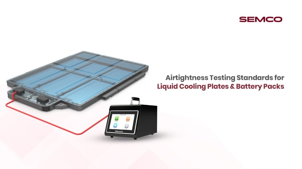
Furthermore, previous technologies were slow and inefficient in pressurizing and charging. Innovative solutions, such as the integrated airtightness testing system for lithium battery packs launched by Hairui, as shown in the diagram, consist of a pressurizing pump, an integrated airtightness tester, and quick connectors. With a testing range of 0-2MPa, it integrates high and low pressure testing functions, meeting the testing pressure requirements of direct-cooled/liquid-cooled plate components and the entire battery pack. A single device can easily handle the airtightness testing of the entire battery pack.
Integrated airtightness testing system for lithium battery packs

Air tightness testing standard setting
In IP68 protection rating, IP stands for Ingress Protection. The first number is the solid state protection rating, with 6 indicating no dust ingress. The second number is the liquid state protection rating, with 8 indicating that after being immersed in water under specified pressure for a specified time, the amount of water entering the casing will not reach a harmful level. The IP68 testing standard for power batteries is that the test piece is placed in water at a depth of 1m and submerged for 1 hour. The passing standard is that no water enters the internal structure.
The IP68 immersion test is time-consuming, destructive to power batteries, and poses certain safety risks, making it unsuitable for final testing of power batteries. Currently, major OEMs and battery manufacturers use airtightness testing to ensure that power batteries meet IP68 requirements. Most domestic OEMs and battery manufacturers currently use the voltage drop method to test the sealing performance of power batteries. The advantages of the voltage drop method are that it only requires a clean compressed air source, has low testing costs, is simple to operate, has low equipment costs, and is highly efficient. The disadvantage is that the voltage drop method is highly dependent on the internal volume of the power battery, and the allowable voltage drop value varies for different battery systems.

Appropriate airtightness testing standards are needed to meet IP68 requirements. The formulation of these standards requires consideration of the relationship between pressure drop and leakage rate, as well as the relationship between orifice diameter and leakage.
Conclusion
When the diameter of the pinhole is ≤0.01mm and the number of pinholes in the same area is ≤6, the power battery can meet the IP68 requirement. Under the same test conditions, the maximum allowable leakage increases with increasing inflation pressure; When the maximum leakage is constant, the larger the internal volume of the power battery, the smaller the allowable pressure difference.
To ensure that the power electrical system meets the IP68 requirements, the maximum leakage rate of the power battery during the airtightness test is ≤27cm3/min@5kPa. The leakage value needs to be adjusted accordingly depending on the test pressure. Once the internal space of the battery system is determined, the allowable leakage differential pressure can be calculated using the ideal gas calculation formula. The sealing performance of a power battery is closely related to the structure of the housing. Even after the maximum allowable leakage is theoretically calculated, a submersion test is still required.
Contact Semco Infratech to discuss your EV & BESS manufacturing requirements and discover how automatic assembly solutions can enhance your production efficiency, ensure product quality, and accelerate your path to market competitiveness.
