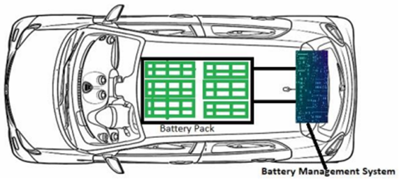
Part 1: Electric door switches for cars
What do Lock, On, and Start mean on the electric door switch of the car, and where does it control? The above picture actually contains 4 power modes, called LOCK, ACC, ON, and START, which are written for car owners and users, in fact, in the automotive electronics industry, they correspond to OFF mode, ACC mode, RUN mode, and CRANK mode.

Part 2: Three power modes for automotive systems.
When discussing technical issues, I often hear people talk about KL15 and KL30, will they be confused, I don’t know what people mean. Anyway, I experienced it, and changed the diagram on the circuit drawn by others, the wake-up line was originally connected to KL15, I said how come there is no switch, I think others drew it wrong, I added a switch between the online and KL15 and made a joke. In fact, K LR, KL15, and KL50 represent the three power modes of the automotive system. ACC mode for KLR automotive power suppliesKL15 car in Run modeKL50 car in Crank modeKL30 Constant power (positive battery)KL31 Constant negative (negative of the battery)Simply put, KL30 and KL31 are the positive and negative poles of the car battery, while KLR, KL15, and KL50 represent the three power modes of the automotive system.
Buy Now: Semco Infratech – SI Battery Charge & Discharge Cabinet Tester – SI BCDS 100V 20A 4CH.
KL | Correspondence | mode | illustrate |
/ | LOCK | OFF mode of the car | Off: The whole car does not supply power except for the constant fire (such as emergency lights, memory functions of the clock, etc.). |
KLR | ACC | ACC mode for automotive power supplies | Radio, start function, radio |
KL15 | ON | RUN mode for cars | Start function, air conditioning, and lower windows |
KL50 | START | CRANK mode of the car | Ignition gear |
KL 30 (also known as B+ or permanent positive) has a battery voltage on a permanent basis. After the battery is installed and connected, this branch of the wire harness remains powered after the ignition switch is turned off and the ignition key is unplugged and can only be disconnected by a switch or relay. For example, the flashing warning switch is powered by the KL 30.
KL 31 Constant negative (negative of the battery): The negative terminal post of the battery is connected to a separate grounding wire and the body steel plate, also known as KL 31 (ground)
OFF mode: It is the LOCK in the figure above, which means that the vehicle power supply is not energized, and the vehicle can network is generally in a dormant state.
ACC mode: The ACC corresponding to the above figure, is the abbreviation of Accessory, the vehicle is powered on, the vehicle is powered on, the can network will also wake up and start transmitting signals, but the engine is not started, the vehicle is basically connected to a 12V power supply voltage, at this time the window is available, the air conditioner can be turned on (but because the generator is not turned on, the air conditioning refrigeration and the heating compressor has no effect, only the blower is blowing).
CRANK mode: corresponding to the START figure above, the engine ignition state, that is, the engine has started, in actual operation, is to screw the key to the end, and when the engine ignition is successful, the keyhole bounces back to the ON in the picture above, which is the RUN mode below.
RUN mode: corresponding to the ON in the picture above, the engine is in operating mode, at this time the generator is also running, the battery is charged, and the air conditioning cooling and heating are available at this time.
The above 4 modes, in the keyless start system, are the same, you can use your own experience to press the power on to enter the ACC mode, the long press ignition is CRANK, and the release after ignition is a RUN mode.
Summary of knowledge points
1. Four gears of ignition switch, LOCK (off gear), ACC (accessory gear), ON (ignition gear), START (start gear).
2. After locking the car, the key will be in the LOCK state, at this time, the key door not only locks the direction but also cuts off the power supply of the whole car.
3. The ACC state to turn on the power supply of some electrical equipment of the car, such as CD, air conditioning, etc.
4. When driving normally, the key is in the ON state, and all circuits of the whole car are in working condition. The START gear is the engine starting gear, which will automatically return to normal after starting, that is, the ON gear. IG1 and IG2 are both ON files.
5. Off The whole car does not supply power except for constant fire (such as emergency lights, memory functions of clocks, etc.).
6. ACC is an accessory file, and some onboard auxiliary equipment is powered by electricity, such as audio-visual systems, instrument lights, lights, etc. That is to say, where the car stops, the engine does not turn, except for the air conditioner can not be used, and the equipment in the car can basically be used.
7. IG-on is a car ignition gear, which increases the ignition function of the engine on the basis of ensuring ACC power supply.
8. ST is the starting gear, which mainly supplies power to the engine starting system, and generally cuts off the circuit of the ACC gear to ensure the smooth start of the engine.
9. AM1 and AM2 are normal electricity entering the ignition switch from the front compartment distribution box.
10. When the ignition switch hits the ACC gear, AM1 and ACC are turned on, when the ignition switch hits the ON gear, AM2 and IG1 are turned on, AM1 and ACC, IG2 are on, when the key hits the START gear, AM1 and ACC, IG2 are disconnected, AM2 and IG1, START are on.
Buy Now: Semco Infratech – SI Battery Management System Tester – SI BMST 1-32S 60/120A with cabinet
Part 3: Wake-up signals inside and outside the BMS
Wake-up source division inside and outside the BMS
The power supply and wake-up of the control board are as follows: the power supply comes from the constant power KL30, and the wake-up source may have many ways, from the inside or outside; And the type may be level wake-up, edge wake-up, or resistance signal, etc.; Specific to the device that is woken up on the control board, it may be a power chip or a single-chip microcomputer.

a Wake up the BMS wiring diagram when the ignition switch is ON gear.
b VCU hard-wire wake-up signal
Sometimes the BMS may wake up through the VCU after sleeping: one case is that KL15 wakes up the VCU first, and then wakes up the BMS through the hard wire signal of the VCU; in addition, after sleeping, the VCU detects some fault conditions and wakes up the BMS through a hard-wired signal.
c AC charging CC wake-up
It is the gun wake-up, CC for the slow charge of the charging connection confirmation signal, in the previous article has detailed the process of overcharging connection, it is a resistance signal, the resistance value represents whether the circuit has been connected, and cable capacity information. If the CC detection circuit is placed on the BMS, it needs to reserve the CC wake-up function.
d OBC hard-wires wake-up signal. This is also the scene of AC charging, and there is a possibility that the CC detection circuit is on the OBC; After inserting the gun, the OBC is awakened; Then in order to further wake up the BMS, it is necessary to output a hard-wire wake-up signal from the OBC, which is not much to say.
e DC charging CC2 wake-up \A+ wake-upSimilarly, DC charging also has a gun wake-up, i.e. CC2 wake-up. It is also a resistance signal, and this detection and wake-up circuit is generally on the BMS, which has been described in detail in the previous article.
f CAN bus wake-up Generally refers to the vehicle power CAN bus, after the BMS sleeps, when there is a specific message on the bus, the BMS CAN transceiver will output a wake-up signal INH, waking up the BMS control board on the power process.
g sampling board fault wake-up Some OEMs have such a demand: when the vehicle is powered down and the BMS enters sleep, the sampling board needs to periodically inspect the battery, and if a fault is found, the sampling board will output a wake-up signal to wake up the control board, and then enter the corresponding processing procedure. For example, in the figure below, the MC33664 is used to wake up the microcontroller. h T-BOX wake-up i RTC wake-up

Some BMS controllers have real-time clock circuits for timing, when the timing accumulates more than a certain set value, the RTC will output an alarm wake-up signal, wake up the controller for some self-test actions, etc. (the figure below comes from the NXP official website), as shown in the INT pin in the figure below
Summary: In order to make a product on the same platform, we need to reserve some possible wake-up source matching circuits, and we need to be familiar with different types of wake-up sources.
More Articles:
Lightweight Technology For Battery,
liquid leakage analysis of soft pack lithium,
what are the functions of the battery pack,
Failure analysis of lithium batteries is a science,
Overview of Lithium Batteries,
The packaging form of lithium-ion battery is better,
Causes Reconditioning Of Battery Vulcanization,
Lithium-ion Battery Process Details,
Lithium battery overcharge mechanism and anti-overcharge measures.,
Factors Affecting The Performance of High Power Lithium-ion Batteries,
Electrical measurement of lithium-ion batteries,