


Introduction
Battery Pole piece coating generally refers to a process in which a uniformly stirred slurry is evenly coated on the current collector, and the organic solvent in the slurry is dried. The effect of coating has an important impact on battery capacity, internal resistance, cycle life and safety.
2.1 Introduction of several coating processes
2.2 Coating window meaning
2.3 Extrusion coating process details
2.4 Coating Common Defect Analysis
2.5 Extrusion Coating Simulation Example
Point Defects in Pole Piece Coating
1. Stomata

- Pinhole defects caused by air bubbles in the wet film from the inside
- The layer migrates to the membrane surface, where it ruptures to form pinholes detect.
- Air bubbles mainly come from stirring, coating liquid transportation and coating Procedure.
2. Foreign body Shrinkage
The surface tension of foreign particles is low, and the coating liquid migrates around Various particles (dust, oil, metal particles, etc.) produce. The presence of foreign particles causes the particle surface. There is a low surface tension region in the wet film at Emission-like migration around the particles to form shrinkage points shape defect. The main preventive measures are: filter the coating liquid to remove Iron, environmental dust control, substrate surface cleaning.
3. Aggregates

The slurry is not uniformly stirred, and the conductive agent is not dispersed, which occurs when agglomerates are formed such defects. The surface of the slurry pole piece containing CNT is rougher and the dispersibility is not good.
Linear Defects in Pole Piece Coating
Coated pole piece scratch defect
1. Scratches

Linear Thin areas or leaky foil Lines parallel to the coating direction
Possible Causes
- Foreign objects or large particles get stuck between the slits,
- In the gap or on the coating gap base material amount not good, cause difference,
- The object is blocked in the coating gap between the coating roller and the Die Lip Damage.
Counter Measures
- Slurry filtration to remove large particles
- Remove particles from lips or coating gaps
Linear Defects in Pole Piece Coating

2. Vertical Bar
Flat with coating direction Row the ripples
Possible Causes
- Usually occurs near the coating window,
- Speed, Spend, Upper limit, thin coatings are more noticeable.
Counter Measures
- Adjust slurry viscosity
- Drop low coating speed Spend
- Drop Coating between low and back rolls gap
Edge Defects in Pole Piece Coating
3. Thick Edge
During the coating Process, the edge is thick and the middle is thin.
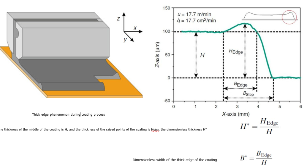
Pole Piece coated thick edge defect

The reduction of the coating gap G can limit the thickness and width of the thick edge coating, and the reduction of the slit size can increase the size of the slurry. At the exit speed of the die, the drag force ratio D of the slurry is reduced, thereby reducing the dimensionless thickness H* of the thick edge coating, but the size of the slit becomes smaller, and the pressure inside the die is greater, which is more likely to cause the die. The expansion of the outlet shape, and thus the lateral thickness non-uniformity of the coating, requires the cooperation of the coating equipment with higher precision.
Pole Piece Coated Thick Edge Defect
Possible Causes
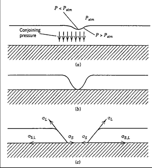
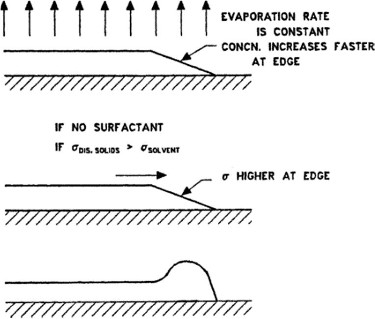
When extruded from the die, the viscoelastic slurry fluid will Expansion due to additional stress on the die edge wall effect, the slurry expansion effect at the edge is more obvious, which leads to thick edge phenomenon occurs.
When the coating dries, it dries at the same rate everywhere, while the edges. The solvent evaporates faster at the edge, so the edge composition changes faster.
If there are no additives such as surfactants in the slurry, or the surface tension of the dispersed particle suspension is greater than that of the solvent. At surface tension, the slurry flows towards the edges, eventually resulting in a thickedge phenomenon.
Solution
The reduction of the coating gap G can limit the reduction of the thick edge coating thickness and width.
Reduce the surface tension of the paste, such as adding interfacial activity agent, adjust the viscosity, etc., to inhibit the slurry to the drying process Edge casting.
Optimized slot gasket outlet shape to change slurry flow. Velocity direction and magnitude to reduce the stress state of the edge slurry state, reducing the edge expansion effect of the slurry. Edge Defects in pole piece coating
4. Trailing

| (g/m) | 50 | 70 | 90 | 110 | 130 | 160 | 180 | 200 |
| (mm) | 0~2 | 0~3 | 0~3 | 0~3 | 0~4 | 0~6 | 0~8 | 0~10 |
Possible Cause
- Poor slurry flow leading to tailing
- The back or applicator gap is not parallel
- Extrusion head/roller distance
- Tension in operation
- The back roller bounces too slowly
Counter Measures
- Adjust slurry properties
- Adjust the back roller applicator gap
- Increase back roller bounce speed
More Articles:
Introduction to Cell Balancing System,
Intercontinental Battery Circle,
Application of Isolation testing Technology,
Battery separator material,
History of Lithium Battery Development,
Production problems of lithium batteries,
Aging Mechanisms of Li-ion Batteries.,
Principles of Power Battery System Design,
Battery Pole Piece Coating Process,