


Thermal Runaway Mitigation Strategies for Li-ion Batteries: Failure Mechanisms, Materials, Cell Design, PACK, BMS
Introduction
Lithium-ion batteries are commercially successful power sources for a variety of applications. However, the characteristics of lithium-ion batteries make them prone to thermal runaway, which can lead to fires and explosions. To mitigate safety hazards before thermal runaway occurs, various strategies have been applied to battery cells and battery packs. This article reviews safety strategies for lithium-ion batteries, including PTC thermistors, PTC electrodes, current interruption devices, safety vents, protection circuits, shutdown separators, electrolyte additives, safety electrolytes, and battery packaging. Passive protection design and battery management system. Triggers, protection mechanisms, disadvantages, and applications of representative strategies are discussed, and potential future risk mitigation approaches are explored. This article mainly includes the following contents:
The characteristics of different forms of batteries and the thermal runaway process of Li-ion batteries are outlined. PTC thermistors and PTC electrodes in Li-ion batteries are introduced.
The different working mechanisms and some representative designs of CID are introduced. The safety discharge design of different forms of lithium-ion batteries is introduced.
The application of the protection circuit in the battery is introduced.
Additional safety strategies in Li-ion batteries are provided, including shutdown separators, electrolyte additives, and safe electrolytes.
Safety strategies for Li-ion battery packaging are discussed.
Current safety strategies are summarized and future risk mitigation prospects based on lithium-ion battery technology trends are discussed.
| Thermal runaway of lithium-ion batteries |
A lithium-ion battery consists of a cathode, an anode, a separator, a current collector, an electrolyte, and a battery casing. There are four basic battery formats for current commercial lithium-ion batteries. Cylindrical, square, pouch and buttoned forms.

A key scientific focus of battery safety research is thermal runaway, which can cause a catastrophic fire or explosion. Many findings report that the thermal runaway mechanism of Li-ion batteries is a chain reaction of uncontrollable temperature rise. Heat generation is unavoidable due to electrochemical reactions inside the battery. During normal operation, the heat generated can be dissipated over time and the battery temperature can still be controlled. However, if the battery is operated in an abnormal mode, such as overcharging, external heating and penetration, the heating will increase significantly. Natural heat dissipation cannot release all the heat generated in time, and the battery temperature will rise significantly.
If the temperature of the battery is close to 130-150°C, the components inside the lithium-ion battery are easily decomposed. For example, the initial decomposition of the solid electrolyte interphase (SEI) on the anode electrode occurs at around 80 °C, the electrolyte starts to decompose at around 100–120 °C, while the melting of polyethylene (PE) and polypropylene (PP) based separators The temperature is about 135°C. Once the electrolyte is burned, large quantities of combustible hydrocarbon gases, including H , CH , C H and C H , are produced and may be ignited at high temperatures. If the separator melts and an internal short circuit occurs, the electrical energy stored in the battery is instantly released, generating more heat and gas. These side reactions exacerbate the abnormal rise in temperature, which in turn promotes a chain reaction until thermal runaway occurs.
Lithium-ion batteries are prone to thermal runaway under elevated temperature, overcurrent loads, excessive internal pressure, and overvoltage conditions. When thermal runaway occurs at the battery level, the consequences vary across battery formats. For example, cylindrical or prismatic cells contained in rigid casings can rupture or explode during thermal runaway, while pouch cells are more likely to swell or catch fire. When cells in series or parallel configuration are placed in battery packs, thermal runaway of a single cell can propagate to adjacent cells, causing catastrophic failure. Faced with this challenge, different types of security strategies are applied at the cell level and the packaging level. At the battery level, safety strategies can be divided into two categories according to their main functions in the battery. The first category is dedicated safety strategies, such as PTC, CID, safety valves, and protection circuits, which are designed to mitigate safety hazards. The second category, supplementary safety strategies, are basic battery components with safety features; these components include shut-off separators, electrolyte additives, and safe electrolytes. At the encapsulation level, security policies can be divided into passive protection and preventive protection. Battery packs with vent structures and fire-resistant materials are designed to prevent or reduce damage in the event of thermal runaway. BMS is implemented into the battery pack to provide preventative protection before thermal runaway occurs. The following sections present a detailed review of lithium-ion battery safety strategies.
Positive Temperature Coefficient Thermistor
IEEE 1725-2011 defines a positive temperature coefficient as “an element that has the characteristic of a sudden and large increase in resistance when the device reaches a specified temperature and/or current”. PTC thermistors in Li-ion batteries are passive resettable devices that protect the battery from overcurrent conditions such as external short circuits. This section will discuss PTC thermistors in Li-ion batteries, the working mechanism of PTC thermistors, and PTC electrodes.


PTC thermistors are common protection devices found in most commercial cylindrical cells, but not in commercial prismatic or pouch cells. A PTC thermistor in a cylindrical battery is a passively resettable device that suppresses high current surges and prevents overcurrent. When it is triggered, it temporarily disables the battery, and when the danger is removed, it returns to a conductive state. Some prismatic batteries have external PTC devices attached to the battery case to limit the current. Lithium-ion batteries with PTC thermistors are safer than batteries without PTC thermistors, but PTC thermistors cause higher battery resistance, resulting in more heat loss. While PTC thermistors have proven effective at the battery level, they are ineffective in large multi-cell battery configurations when subjected to high voltage short-circuit conditions. PTC electrodes have been shown to be a good solution to improve the response of PTC to high temperature. However, more work needs to be done to minimize the impact on electrode conductivity and battery performance.
Current Interruption Device
In lithium-ion batteries, the CID is a protective device built into the battery to eliminate the hazards of high internal pressure or temperature. When battery pressure or battery temperature exceeds a predetermined level, it will break the electrical connections in the battery. According to the reaction mechanism, CIDs can be roughly divided into two categories, namely pressure-responsive CIDs and temperature-responsive CIDs.


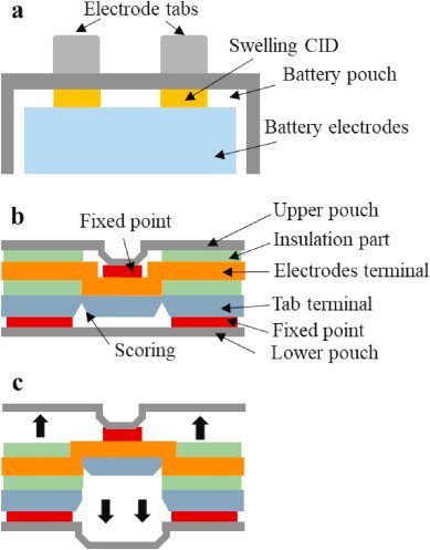


CID protects batteries from excessive internal pressure or temperature and has been implemented in commercial batteries in different formats. Pressure-responsive CIDs are characterized by weak connections in the circuit, which can be cut off once the internal pressure reaches a predetermined level. Temperature-responsive CIDs cut circuits by blowing fuses at excessively high temperatures determined by the melting point of the fuse material. The implementation of the CID inevitably increases the resistance of the battery and reduces the energy density; therefore, the top plate of many 18650 batteries is both the CID and the safety vent to save weight and space. CID effectively reduces the occurrence of single cell thermal runaway, but may not work when the module includes multiple cell series and/or parallel configurations. There is already evidence that CID does not protect the battery from thermal runaway under the overcharge condition of the high voltage module.
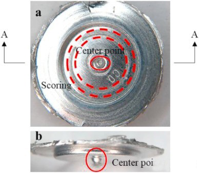
Safety Vent
During thermal runaway, the accumulation of gas increases the internal pressure of the battery, which may further rupture the battery casing if the pressure is not released properly. The safety vent relieves the internal pressure of the battery by venting the generated gas. The vent is a weak point designed on the battery case to safely “exhaust” the gas. The International Electrotechnical Commission (IEC) 62133 standard defines “venting” as “the release of excess internal pressure from a cell or battery in a manner designed to prevent rupture or explosion”. The IEEE 1725 standard states, “The battery shall be designed to include a consistent venting design or mechanism, such as aluminum foil, edges, seams, or markings. The venting mechanism shall be designed to minimize projectiles and maximize retention of the battery’s contents”.
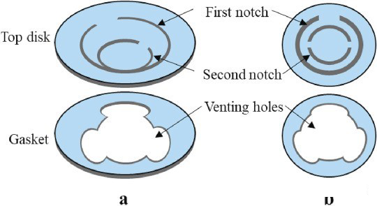


When the internal pressure of the cell reaches a predetermined high level, the safety valve opens to prevent rupture of the entire cell, e.g. 113-128 psi (8.5 ± 0.5 kg./cm2) for square cells and 406 psi (2.8 kgf/cm2) for 18650 cylindrical cells Mpa). Various notches or grooves are preset in different cell structures to ensure that the safety vents open at predetermined pressure levels. However, if the only safety vent is blocked and the internal pressure cannot be released in time, the accumulated pressure may rupture the battery case or even cause an explosion. To solve this problem, battery manufacturers, such as LG and Sony, have added a bottom vent to the cylindrical battery of some models. This design improves venting efficiency and minimizes the thermal impact of individual cell rupture in the battery pack. Multiple safety vents will be more common in different battery formats in the future, but may increase the risk of electrolyte leakage. Once the safety vent is open, the battery will leak electrolyte, which itself is potentially harmful to the environment around the battery.
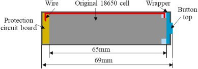
Protect the Circuit
Another strategy to improve battery safety is to protect circuits against overcharge, over discharge overcurrent, and overtemperature. IEEE 1725-2011 lists “protection circuits” as an additional risk mitigation method for overvoltage, undervoltage, electrostatic discharge, and overcurrent for cells and battery packs. This section discusses various protection circuit designs for Li-ion cells and battery packs.


Additional Safety Strategies for Lithium-Ion Batteries
The main function of PTC thermistors, CIDs, safety vents, and protection circuits is to protect Li-ion batteries from thermal runaway, and they are the main mitigation strategies for Lithium batteries safety hazards. Some components in lithium-ion batteries can also improve battery safety. For example, separators can shut down batteries in the event of elevated temperatures, and electrolytes with additives can protect batteries from overcharging and catching fire. This section describes additional safety strategies for Li-ion batteries.
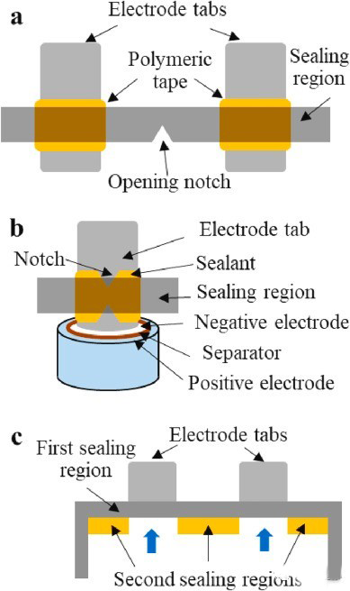
The separator is an important component of lithium-ion batteries, which can determine battery performance and safety by affecting battery kinetics. A separator is placed between the two electrodes to maintain the distance between them and avoid electrical shorts. At the same time, the separator is wetted by the electrolyte, allowing ion transport between the two electrodes during charging and discharging. Separator shutdown refers to stopping the electrochemical reaction between two electrodes at a temperature slightly below the thermal runaway trigger temperature, while maintaining a physical barrier between the two electrodes.
The electrolyte in lithium-ion batteries provides a transport environment for ions between the two electrodes during charging and discharging. They consist of one or several conductive lithium salts (e.g. LiClO 4 , LiAsF 6 , LiBF 4 , LiPF 6 ) dissolved in a non-aqueous solvent . The composition of the electrolyte will affect the formation and growth of the SEI layer on the surface of the positive and negative electrodes, which is related to battery performance and safety issues. Additives are substances that are added to the electrolyte at low concentrations of 0.5-10 wt% to alter its properties. Ideally, they should have no effect on the cycling performance of the battery. Various electrolyte additives, such as overcharge protection additives and flame retardant (FR) additives, have been investigated to improve the safety of Li-ion batteries.
Conventional liquid electrolytes, mainly composed of lithium salts and organic solvents, offer excellent electrochemical performance, as well as poor thermal instability. Electrolyte additives have played a limited role in improving battery safety by changing the properties of conventional electrolytes. To obtain safe electrolytes, replacing current flammable electrolytes with novel electrolytes, including ionic liquids, polymer electrolytes, and inorganic solid-state electrolytes, can effectively improve battery safety.
Safety Strategy for Lithium-Ion Battery Packs
The PTC and CID built into commercial lithium-ion batteries are proven to be reliable for single cells, protecting the battery from hazardous conditions. However, single cells are not suitable for large electrical applications. For example, the battery pack provided by Tesla is made up of 7,104 cylindrical cells. PTC and CID in multi-cell configurations, including series or parallel, do not always protect the cells from thermal runaway. NASA’s test program has confirmed that PTC and CID failed to mitigate thermal runaway in multi-cell configurations under various test conditions. With the rapid growth of the world electric vehicle market, the safety requirements on the packaging level are also increasing. In particular, the propagation of thermal runaway to adjacent cells in a Li-ion battery pack can be catastrophic.


A battery management system (BMS) is an electronic system that monitors and controls the status of individual cells or battery packs. A BMS provides multiple functions: performance management (such as battery monitoring and balancing), protection (such as thermal management), state estimation (such as state of health (SOH) and state of charge (SOC) estimation), fault diagnosis (such as fault diagnosis and prediction) and communications (such as data storage and transmission). This section summarizes the functions most relevant to battery safety, including thermal management, battery state estimation, and troubleshooting.
Future Trends in Battery Safety Strategies
PTC thermistors, CIDs, safety vents, and protection circuits are specifically designed to improve battery safety, which inevitably increases battery resistance and reduces mass/bulk density. They are being developed to have lower resistance, lighter weight, smaller space and lower cost. While a single safety vent is commonly used to relieve internal pressure and prevent explosions in all types of commercial batteries, the increase in battery energy density places higher demands on venting efficiency. Sony and LG have added a bottom vent to some cylindrical batteries to improve venting. Multiple safety vents may become more common in the future to cope with the increase in battery energy density.
The global BMS market is expected to grow substantially with the growth of lithium-ion battery applications. There are various types of BMS depending on the battery form factor, components and application. The lack of BMS standards is likely to limit the growth of the BMS market in the coming years. The protection of battery packs, such as packaging design, PCM, thermal management system, battery state estimation module and fault diagnosis module, requires adding weight and space to the battery pack. Therefore, standardization, compactness and effectiveness will be the pursuit of the next stage of commercial BMS.
Conclusion
Currently lithium-ion batteries use flammable liquid electrolytes with inherent safety risks. The search for safer electrolytes has been extensively studied, ranging from non-flammable liquid electrolytes, liquid-solid electrolytes to all solid-state electrolytes. Although the gel polymer electrolyte combines the advantages of liquid electrolytes and solid electrolytes, it does not perform well in terms of long-term cycle life. The technology of inorganic solid-state electrolytes is still developing, while showing great promise and may be the ultimate solution to eliminate the harm of lithium-ion batteries.
Cell-level safety strategies will continue to be used in commercial batteries in the near future. Safety strategies will be extended to different battery formats and towards low resistance, light weight, small space and low cost. Improvements in separator materials, electrolyte additives, and BMS can improve battery safety. Once batteries become refractory in the future, a likely trend in battery safety will be to remove safety devices in order to achieve higher energy densities without introducing safety concerns.
More Articles:
BMS Battery Management System,
Battery Electrical Performance Test,
Safety Analysis of Li-Ion Battery,
IEC Battery Safety Standard for Power Batteries,
Electric Vehicle Basics,
Thermal Runaway Mitigation Strategies for Li-ion Batteries,