


Battery Power Zone traditionally is the power system that is divided into three major systems: power generation, transmission, and distribution. The power generated by the power generation system is transmitted through the transmission system and finally distributed by the distribution system to each user.
Generally speaking, the Battery Power Zone system that exports the power system from the voltage relief distribution substation (high-voltage distribution substation) to the user is called the distribution system.
A distribution Battery Power Zone system is a power network system composed of a variety of distribution equipment (or components) and distribution facilities to transform voltage and distribute electricity directly to end users.
Composition of the Battery Power Zone distribution system
The Battery Power Zone distribution system can be divided into three parts: high-voltage distribution system, medium-voltage distribution system, and low-voltage distribution system. Because the distribution system, as the last link of the power system, is directly aimed at end users, its improvement is directly related to the reliability and quality of electricity consumption of the majority of users, so it plays an important role in the Battery Power Zone system.
The voltage level of China’s distribution system is stipulated in the Guidelines for the Planning and Design of Urban Power Grids. 220kV and above voltages are transmission and substation systems, 35, 63 and 110kV are high-voltage distribution systems, 10 and 6kV are medium-voltage distribution systems, and 380 and 220V are low-voltage distribution systems.
How the power distribution system works
The safe operation and management of transformers is the focus of our daily work. Through the summary of the experience of abnormal operation of transformers and the analysis of common faults, it will be conducive to timely and accurate judgment of the cause and nature of failures, and timely and timely and effective measures to ensure the safe operation of the equipment. Transformers are extremely important electrical equipment in the transmission and distribution system. According to the operation and maintenance management regulations, transformers must be inspected regularly in order to understand and master the operation of transformers in a timely manner and take effective measures in time to strive to eliminate faults in the budding state, so as to ensure the safe operation of transformers. The abnormal operation of the transformer and common failures are as follows:
- The sound of the transformer is abnormal.
- Under normal load and normal cooling mode, the oil temperature of the transformer continues to rise.
- Significant changes in the color of transformer insulation oil.
- Oil injection in the oil pillow or explosion-proof pipe.
- There is a three-phase voltage imbalance.
- The occurrence of relay protection.
- Flashing and explosion of insulated porcelain casing.
- The failure of the switch.
Basic methods of the power distribution system
According to the various protection methods and terminology concepts stipulated by the IEC, low-voltage power distribution systems are divided into three categories according to different grounding methods, namely TT, TN, and IT systems, as described below.
- Power supply system for TT which stands for a protective grounding system, often known as a TT system, that directly grounds the metal casing of electrical equipment. The first symbol T denotes that the earth is directly connected to the power system’s sexual point, while the second symbol T denotes that the load equipment’s exposed metal conductor that is not connected to the charged body is also directly connected to the earth but has nothing to do with how the power system grounds itself. Protective grounding is the term used for all loaded groundings in TT systems. These are the features of this power supply system.
- When the metal shell of the electrical equipment is charged (the phase line collision case or the equipment is damaged by insulation leakage), the risk of electric shock can be greatly reduced due to grounding protection. However, the low-voltage circuit breaker (automatic switch) may not be able to trip, causing the shell of the leakage equipment to the ground voltage higher than the safe voltage, which is a dangerous voltage.
- It can be challenging to spread awareness of the TT system when the leakage current is quite low since, even with a fuse, it might not be fuseable.
- The grounding device for the TT system uses a lot of steel and is lab- and material-intensive to recover.

Nowadays, some construction units use the TT system. When the construction unit borrows its power supply for temporary power consumption, it uses a special protection line to reduce the amount of steel that needs to be grounded.
The characteristics of separating the newly added special protection line PE line from the working zero-line N are:
- The shared grounding line has no connection with the working zero line;
- During normal operation, the working zero line can have current, while the special protection line has no current;
- The TT system is suitable for ground protection occupies scattered places.
- TN power supply system: This power supply system is a protection system that connects the metal shell of electrical equipment to the working zero line. It is called a zero-protection system, represented by TN. Its characteristics are as follows.
- The zero-connection protection system can boost the leakage current to short-circuit current once the equipment’s outer shell has been powered up. This current is 5.3 times as big as the TT system’s current. In actuality, the problem is a rather short circuit. The low voltage circuit breakers debacle will instantly move and trip, and the barrier equipment’s power will be cut off, which is a relatively safe situation.
- The TN system saves materials and working hours, and is widely used in China and many other countries, which shows more advantages than the TT system. In the TN-style power supply system, it is divided into TN-C and TN-S according to whether the protection zero line is separated from the working zero line.
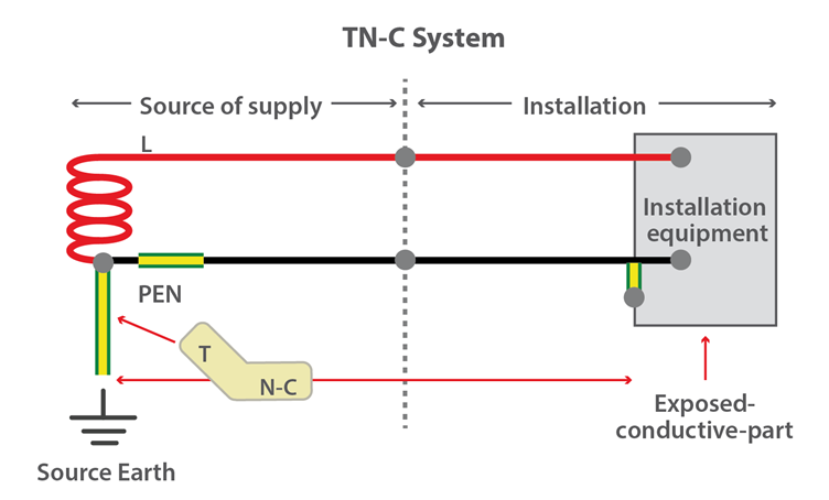
- TN-C power supply system. It uses working zero lines as both zero protection lines, which can be called protective neutral lines and can be represented by NPE.
- TN-S power supply system is a power supply system that strictly separates working zero-line N from the dedicated protection line PE. It is called TN-S power supply system. The characteristics of the TN-S power supply system are as follows.
- When the system is in normal operation, there is no current on the special protection line, but there is an unbalanced current on the zero line. There is no voltage on the PE line, so the zero protection of the metal shell of electrical equipment is connected to the special protection line PE, which is safe and reliable.
- The working zero line is only used as a single-phase lighting load circuit.
- The special protective line PE is not allowed to disconnect the wire or enter the leakage switch.
- A leakage protector is used on the trunk line. The working zero line shall not be repeatedly grounded, and the PE line has repeated grounding, but it does not pass through the leakage protector, so the leakage protector can also be installed on the power supply line of the TN-S system.
- The TN-S power supply system is safe and reliable, and is suitable for low voltage power supply systems such as industrial and civil buildings. Before the construction project starts, “three links and one level” (electricity, water, road and floor – the power supply system must be provided by TN-S).
- TN-C-S power supply system: In the temporary power supply of construction, the PE line can be separated from the main distribution box at the back of the site, TN-C-S, if the previous part was TN-C power supply and the construction specifications require the construction site to use the TN-S power supply system. Following are the system’s characteristics.
- Working zero-line N is connected to the special protection line PE. When the unbalanced current of this line is relatively large, the zero protection of electrical equipment is affected by the zero-wire potential. There is no current from point D to the rear PE line, that is, there is no voltage drop on the section of the conductor. Therefore, the TN-C-S system can reduce the ground voltage of the motor housing, but this voltage cannot be completely eliminated. The size of this voltage depends on the load imbalance of the ND line and ND. The length of this line. The more unbalanced the load and the longer the ND line, the greater the ground voltage offset of the device housing. Therefore, the load imbalance current should not be too large, and it should be repeatedly grounded on the PE line.
- The PE line cannot enter the leakage protector under any circumstances, because the action of the leakage protector at the end of the line will cause the front leakage protector to trip and cause a large-scale power outage.
- Except for the PE line, which must be connected with the N line at the main box, the N line and PE line shall not be connected at all other sub-boxes. Switches and fuses are not allowed on the PE line, nor shall they be used as PE wires.
Through the above analysis, the TN-C-S power supply system is a temporary alternative on the TN-C system. When the three-phase power transformer works well and the three-phase load is relatively balanced, the TN-C-S system is feasible in construction power practice. However, when the three-phase load is unbalanced and there is a special power transformer at the construction site, the TN-S power supply system must be used.
IT-modal power supply system: I indicate that the power supply side is not working grounded or grounded by high impedance. The second letter T indicates the grounding protection of the electrical equipment on the load side.
When the IT power supply system is not very long, the reliability and safety of the power supply is high. It is generally used in places where power outages are not allowed, or where strict continuous power supply is required, such as electric steelmaking, operating rooms of large hospitals, underground mines, etc. The power supply conditions in underground mines are relatively poor, and cables are prone to moisture. Using IT to power the system, even if the neutral point of the power supply is not grounded, once the equipment leaks, the relative ground drain current is still small, which will not destroy the balance of the power supply voltage, so it is safer than the system where the neutral point of the power supply is grounded.
However, if used for a long power supply distance, the distribution capacitance of the power supply line to the earth cannot be ignored. When the load has a short-circuit failure or leakage to energize the equipment shell, the leakage current forms a shelf through the earth, and the protection equipment may not necessarily move, which is dangerous. It is safer only if the power supply distance is not too long. This kind of power supply is rare on construction sites.
More Articles:
BMS Battery Management System,
Battery Electrical Performance Test,
Safety Analysis of Li-Ion Battery,
IEC Battery Safety Standard for Power Batteries,
POWER BATTERY SHELL WATERPROOF DESIGN,
BATTERY SAFETY PERFORMANCE TEST,