


`
Introduction
The invention relates to a coating machine of battery pole piece coating, in particular to automatic machinery for packaging battery pole pieces with an isolating film in the manufacture process of lithium batteries. The coating machine automatic machinery comprises a stand, a positioning mechanism, a feeding mechanism, a filming mechanism, a sealing mechanism and a discharging mechanism, wherein the positioning mechanism adopts a multi-station stepping mode is adopted for the positioning mechanism, and jigs tools are circumferentially arranged for positioning film materials and pole pieces. The pole pieces are put in the jigstools from the feeding mechanism, automatically folded and packaged with by film materials, sealed into bags by the sealing mechanism and collected by the discharging mechanism to be put into a feeding groove. The invention has the advantages of simple and reliable structure, high productivity energy yield, accurate positioning, consistent products and operation automation.
Battery Pole Piece Coating Process
2.1 Introduction of several coating processes
2.2 Coating window meaning
2.3 Extrusion coating process details
2.4 Coating Common Defect Analysis
2.5 Extrusion Coating Simulation Example
Schematic Diagram of the Coating Process
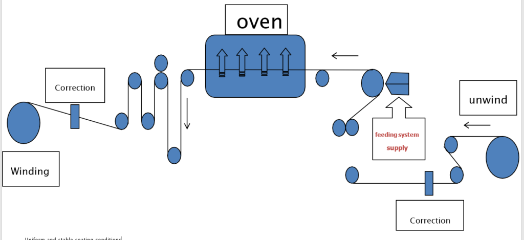
Uniform and Stable Coating Conditions
(1) The properties of the slurry are stable, no sedimentation occurs, and the viscosity and solid content do not change
(2) The feeding and supply of the slurry is stable, and a uniform and stable flow state is formed inside the die or on the coating roller and the transfer roller
(3) The coating process forms a stable flow field between the die head and the coating roller within the coating window
(4) The foil travels stably, no belt slippage occurs, severe jitter and wrinkles: tension and deviation correction control.
2.1 Introduction of Several Coating Process
Blade Coating

The foil substrate passes through the coating roll and is in direct contact with the slurry tank, and the excess slurry is coated on the foil substrate, where the substrate passes through the coating process. Between the roll and the doctor blade, the gap between the doctor blade and the substrate determines the thickness of the coating, while scraping off excess slurry to reflow, thereby forming a uniform coating on the surface of the substrate.
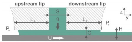
Slot Extrusion Coating Process
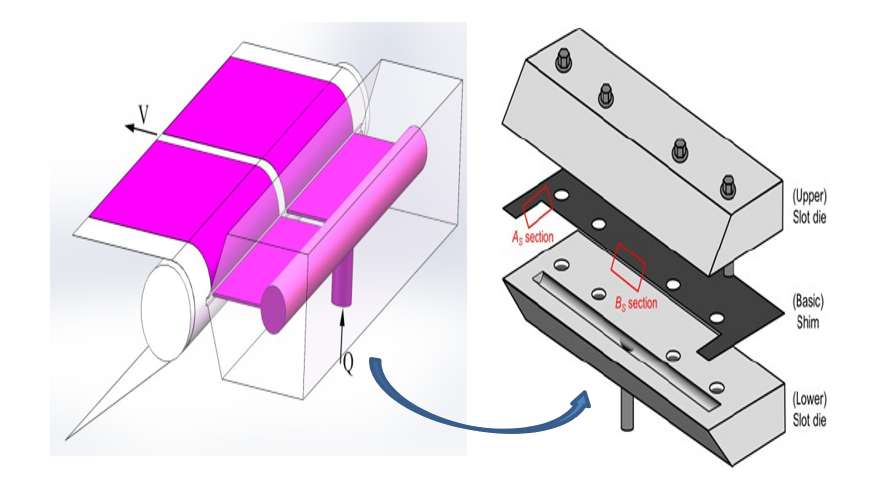
Schematic Diagram of Slot Extrusion Coating
The slurry with a certain flow rate Q enters the inner cavity of the die head from the feeding port of the extrusion head, and forms a stable pressure. It has many advantages, such as fast coating speed, high precision and uniform wet thickness; the coating system is closed, which can prevent the entry of pollutants during the coating process, the slurry utilization rate is high, the slurry properties can be kept stable, and multiple processes can be carried out at the same time. layer coating.
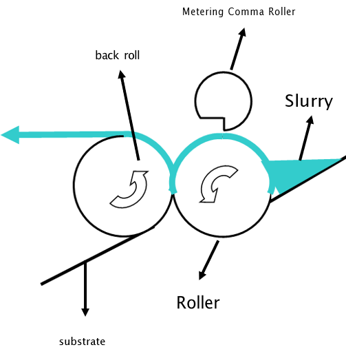
Comma Roll Blade Transfer Coating
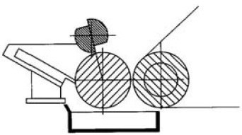
Schematic Diagram of Blade Transfer Coating
The rotation of the coating roller drives the slurry, the amount of slurry transfer is adjusted through the comma scraper gap, and the rotation of the back roller and the coating roller is used.
Transfer Slurry to Substrate
Coating Process
Coated areal density is an important control parameter. The typical commercial battery surface capacity is 2.5-3.0 mAh/cm2. Areal capacity = single-sided areal density x active matter. Mass gram capacity x active substance ratio, Determine the surface density of the negative electrode according to the negative electrode to positive degree, N/P is generally 1.04~1.20
| Positive electrode material | l Gram capacity | true density | one side dense Spend | surface capacity |
| Proportion96% | mAh/g | g/cc | mg/cm2 | mAh/cm2 |
| LCO-140 | 140 | 5.05 | 20 | 2.8 |
| LCO-180 | 180 | 5.05 | 20 | 3.6 |
| LCO-220 | 220 | 5.05 | 20 | 4.4 |
| LMO | 130 | 4.31 | 20 | 2.6 |
| LFP | 160 | 3.65 | 20 | 3.2 |
| LCP | 130 | 3.7 | 20 | 2.6 |
| NCM333 | 160 | 4.75 | 20 | 3.2 |
| NCM523 | 180 | 4.65 | 20 | 3.6 |
| NCM811 | 220 | 4.65 | 20 | 4.4 |
| Li-rich250 | 250 | 4.7 | 20 | 5 |
| Li-rich280 | 280 | 4.7 | 20 | 5.6 |
| Li-rich300 | 300 | 4.7 | 20 | 6 |
| NCA-180 lectrode capacity ratio | 180 N/P | 4.6 | 20 | 3.6 |
| e NCA-200 | 200 | 4.6 | 20 | 4 |
| NCA-220 | 200 | 4.6 | 20 | 4 |
| LNM | 135 | 4.4 | 20 | 2.7 |
2.2 Coating Window
Coating Window: In the actual process, regardless of the slit extrusion. There is a coating window for both pressure coating and transfer coating port, that is, the fluid is in a steady state of flow, and the parameters of the flow field are
The number does not change with time, and stable coating is possible. Process operating range to obtain a uniform coating.
The upper limit of the coating window is mainly affected by the stability of the coating solution effects, such as when the flow rate is insufficient, or the coating speed When the temperature is too fast, the coating liquid bead becomes unstable, and it is easy to produce defects such as air infiltration and transverse waves. When the lower limit of the coating window occurs, such as excessive flow or if the coating speed is too slow, the fluid cannot be carried in time Go away, the coating liquid beads accumulate in large quantities, and it is easy to form water suffocation or sagging.
2.3 Extrusion Coating Window Process
The coating window is the process operating range that can be stably coated to obtain a uniform coating, which is subject to three Influence of class factors:
(1) Fluid properties, such as viscosity μ, Surface Tension, density;
(2) Geometric parameters of extrusion die, such as coating spacing, the die slit size,
(3) Coating process parameters, such as coating speed, slurry feed flow Wait.
Under a fixed flow rate, there is an upper coating speed limit and a lower coating speed limit, between the coating speed, The range between the upper and lower limits is the coating window. The upper limit of the coating window is mainly affected by the stability of the coating liquid. For example, when the flow rate is insufficient or the coating speed is too fast, the coating liquid bead becomes unstable, and defects such as air infiltration and transverse waves are easily generated. When the lower limit of the coating window occurs, if the flow rate is too large or the coating speed is too slow, the fluid cannot be taken away in time, and a large number of coating droplets accumulate, which is easy to form water suffocation or vertical flow.
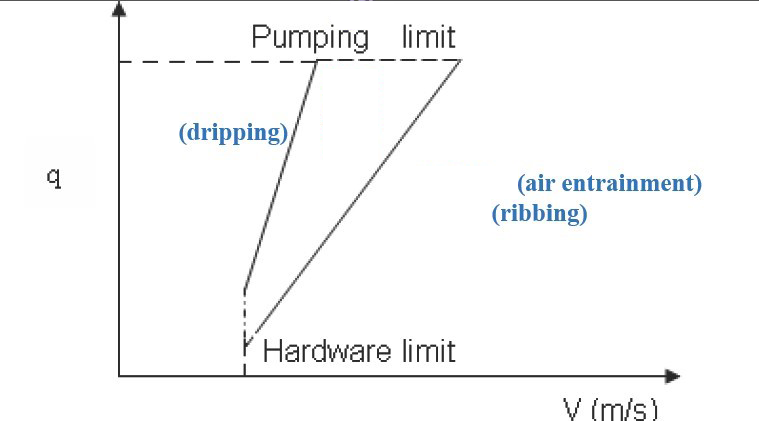
Extrusion Coating Window

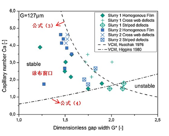
Experiments in the coating window were able to obtain uniform coatings, while the pro-experimental coatings near the coating window boundary or outside the coating window were there are coating defects. In addition, the experimental results are related to the coating window theory.
On model fit. It can be seen from the coating window in the figure that for a certain
For a fixed value of Ca, there is a maximum G* value, that is, there is a maximum G* value. Small wet coating thickness H, when the coating wet thickness is less than this value, no method to produce a uniform coating. In order to obtain a certain coating wet thickness. When the coating distance G is determined, a certain value G* is determined, at this time, Ca must satisfy a certain range (fall within the coating window) to obtain a uniform coating. If the slurry properties are constant (viscosity, surface tension), the coating window has a maximum coating speed, the coating process cannot exceed this speed.
Transfer Coating Window
Blade Transfer Coating Involves Two Basic Processes:
1. The rotation of the coating roller drives the slurry to pass through the gap between the metering rollers. A slurry layer of a certain thickness is formed. This process is a special form of clockwise rolls, where the metering roll If it does not rotate, the speed is zero, and the cross-section of the metering roller is made into a comma. Shape, also called comma scraper. Coating thickness by changing the amuse. The distance between the doctor blade and the coating roll can be adjusted.
2. The slurry layer of a certain thickness passes through the coating in the opposite direction. The roll and back roll rotate to transfer the slurry to the foil to form the coating. This process belongs to the reverse roll coating method There is a certain coating window for these two basic processes
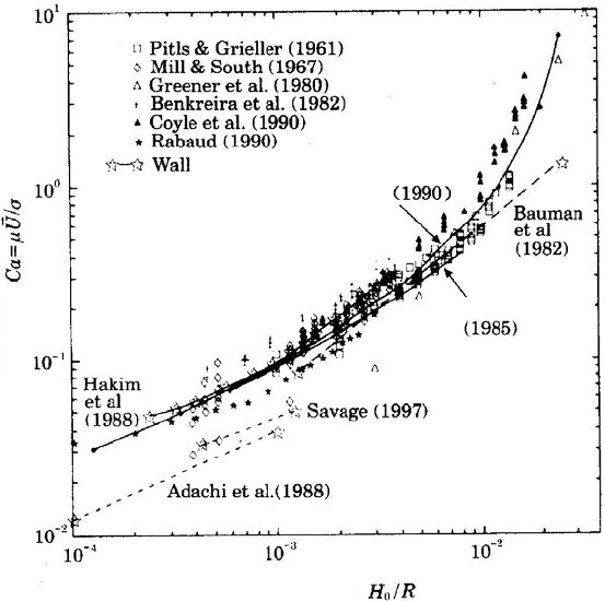

Capillary Number
Ca=μU/σ, μ is the viscosity of the slurry, Is the surface line speed of the coating roller, σ is the surface tension of the slurry fluid. For coating rolls and metering the gap between the rollers, Is the equivalent radius of the two rolls.
In the figure, the lower part of the curve is the uniform coating area, that is, in the capillary number smaller range of values, gap/roll diameter ratio H/When it is larger, it can be uniformly coated, and the coating conditions are improved into the coating window. In pole piece coating, the slurry viscosity ratio larger, so the coating speed is limited and can only be used at lower speed coating. In addition, if the roller diameter has been determined Under certain circumstances, a larger gap is conducive to uniform coating.
Transfer Coating Window

Speed ratio = Vm/Va, Vmis the surface linear velocity of the back roller, Vato paint
The surface line speed of the cloth roller. The stability zone in the figure, which is the reversal Roll coating window, it can be seen that the reverse roll coating window is relatively small exist. During the reverse roll coating process, if the gap between the two rolls is relatively small. The fineness is low enough, that is, when the viscosity or speed is relatively small.
Conclusion
In the case of a relatively wide range of speed ratios, the flow ratio is more stable and can get better coating appearance quality. If the gap is relatively large, it is easy to appear when the coating speed is high air entrainment, with many tiny air bubbles on the coating surface. Sometimes In order to increase the output, to increase the coating speed, it is possible to air entrainment is now occurring. In order to eliminate this problem, the Take the operation method to reduce the gap. too small a gap to allow coating Roller and back roll squeeze each other, additional motor and deceleration added machine load, causing abnormal wear and tear.
More Articles:
Introduction to Cell Balancing System,
Intercontinental Battery Circle,
Application of Isolation testing Technology,
Battery separator material,
History of Lithium Battery Development,
Production problems of lithium batteries,
Aging Mechanisms of Li-ion Batteries.,
Principles of Power Battery System Design,