

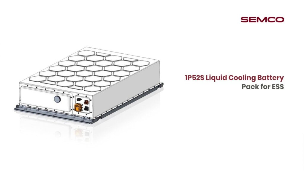
1. Overview & Configuration
The 1P52S lithium battery module consists of 52 prismatic LFP (Lithium Iron Phosphate) cells connected in series, with no parallel strings (1P). This is the industry-standard configuration for BESS energy storage modules used widely in grid-scale applications.

The module typically includes 52 prismatic LFP cells, an internal BMS, a CCS (Cell Contact System) integrated busbar, high-voltage connectors, a liquid cooling plate, fixed structural parts, and a fire/thermal-warning module.
Stage 1 — Cell Incoming Inspection & Pretreatment
Incoming Cell Inspection (IQC)
Upon receipt, every cell undergoes Incoming Quality Control (IQC) before entering the production line.
Required Tests:
- OCV (Open Circuit Voltage): Measure and record the open-circuit voltage of each cell. Reject cells outside the permissible voltage window.
- ACIR (AC Internal Resistance): Measure internal resistance using instruments such as HIOKI BT3562 or equivalent. Binning is performed based on resistance values.
- EIS (Electrical Impedance Spectroscopy): Assess electrochemical state of cells (for high-specification lines)
- Capacity Analysis: Verify rated capacity (314 Ah) against shipping documentation
- Visual Inspection: Check for dents, deformation, electrolyte leakage, terminal damage, or label defects

Cells failing any of the above checks are quarantined and rejected. Passed cells are sorted by binning into matching groups.
Cell Capacity Grading
Cells proceed to a capacity grading cabinet for charge-discharge cycling tests to verify and group cells by actual capacity. This ensures consistent capacity performance across all 52 cells in the series string.
- Each channel can be independently started/stopped
- Data captured and stored via SQL database with MES integration
- Modular design allows easy maintenance and channel expansion

Cell OCV & ACIR Sorting
Sorted cells are scanned (barcode/QR) and passed through an automated OCV & ACIR sorting machine:
- Operator places cell on input belt
- Cell flows to scanning station — barcode/QR code is read and linked to module build record
- Cell flows to test station — OCV and ACIR values are recorded
- Sorting mechanism routes cells into corresponding grouping channels by grade
- Cells that fail are automatically diverted to a reject lane
Acceptance Criteria: Voltage deviation within ±2 mV; internal resistance deviation within ±0.1 mΩ (per manufacturer specification)
Stage 2 — Cell Pretreatment & Surface Preparation
Plasma / Laser Surface Cleaning
Prior to adhesive application or stacking, cell surfaces undergo cleaning to remove micro-contaminants, oxidation layers, and organic residues.
Process Method:
- Plasma Cleaning (corona discharge) or Laser Cleaning/Ablation using a fiber laser
- Cleaning targets: large flat cell surfaces (for bonding), terminal poles, and busbar contact surfaces
- Post-cleaning surfaces must not be touched with bare hands — handle with clean ESD gloves only

Laser cleaning machines deliver high-energy pulses through fiber optic cables to ablate surface contaminants without damaging the substrate. This is critical to ensure strong adhesive bonds and low-resistance laser welds.
Insulation Film / Protective Film Application
- Apply hot-pressed PET insulation film or insulating tape to the required faces of each cell
- Ensure no air bubbles or wrinkles — uniform coverage required
- Insulation must cover all conductive surfaces that could cause unintended electrical contact within the module structure
- Adhesive tape or structural/thermal adhesive is applied to one major face of each cell, depending on the design specification
Thermal Gap Filler / Thermal Adhesive Application
For liquid-cooled 1P52S modules, thermal interface material (TIM) is applied between the cells and the cooling plate surface:
- Apply thermally conductive adhesive (e.g., two-component polyurethane or silicone-based thermal paste) using a precision dual-component dispenser
- Typical application areas: cell bottom face (interfacing with liquid cooling plate), between cell faces when foam/thermal pad is used
- Adhesive must be applied uniformly; dispenser path is CNC-programmed for repeatability
- After application, the assembly moves directly to stacking before adhesive cures (wet bond process), unless a foam pad approach is used (in which case pads are pre-cut and positioned)

Stage 3 — Cell Stacking & Module Structure Assembly
Cell Stacking
All 52 cells are assembled into a precise linear stack:
Manual / Semi-Automatic Process:
- Set up the stacking fixture or jig on the pressing machine
- Load the first end plate (insulated, aluminium or steel) into the jig
- Insert cells one by one in the defined polarity sequence (alternating as per electrical design): verify polarity of each cell before placement
- Place foam pads or thermal adhesive-coated spacers between each cell pair as required
- Insert the second end plate on the opposite end
- Mount side plates (insulation plates) on left and right flanks
Stacking Parameters:
- Stacking pressure controlled by servo motor + screw module + planetary reducer
- Extrusion/compression force: typically 500 kg or as specified (adjustable via 7-inch touch screen PLC control)
- Pressure accuracy: ±0.1 kg using built-in high-precision pressure sensor

Cell Stack Compression & Banding
After stacking, the cell block is compressed and secured:
- Apply compression force to achieve specified cell group pressure (consult design specification for target force in kN)
- Strap the compressed stack with steel strips or plastic-steel strapping bands — typically 2–4 bands per module
- Confirm strap tension is within specification using calibrated tensioning tool
- Scan the stacked module barcode; bind cell serial numbers to the module serial number in MES

End Plate & Side Plate Fastening
- End plates and side plates (pressure plates) are plasma-cleaned before assembly
- End plates placed at opposite ends of the stacked cell block
- Plates are mechanically fastened using bolts (torque-to-spec) or welded, depending on design
- Insert insulation side plates to prevent electrical contact between cells and module housing frame
Stage 4 — Module Terminal Cleaning & CCS/Busbar Assembly
Terminal Pole Laser Cleaning (Pre-Weld)
Before busbar installation and welding, terminal poles of all 52 cells are laser cleaned:
- Use fiber laser cleaner on all positive and negative terminal poles
- Remove oxide layer, contaminants, and residues from the pole surface
- This step is mandatory for achieving low-resistance, high-quality welds
- After cleaning, avoid contact with cleaned surfaces
Polarity Detection
- Perform manual polarity detection across the assembled module to verify correct cell orientation
- Use a multimeter or dedicated polarity tester to confirm that the total module voltage matches the expected 52S open-circuit sum (approx. 52 × 3.2V = 166.4V nominal)
- Any reversal of cell polarity is a critical defect — must be rectified before proceeding

CCS / Busbar Installation
The Cell Contact System (CCS) is the integrated busbar assembly combining conductive busbars, voltage-sensing wires, temperature sensors, and structural brackets into a single unit:
CCS Components:
- Aluminium busbars (for current carrying)
- FPC (Flexible Printed Circuit) or wire harness for voltage/temperature signal acquisition
- Hot-pressed PET insulation films (electrical isolation)
- Injection-moulded or vacuum-formed plastic bracket (structural support)
Installation Steps:
- Inspect CCS assembly for physical defects before installation
- Position CCS on top of the stacked cell assembly, aligning busbar tabs with cell terminal poles
- Use a fixture/jig to hold CCS in exact position during welding
- Verify alignment of each busbar tab over the corresponding cell terminal using vision system or manual check

Stage 5 — Laser Welding
Laser welding is the critical joining process that electrically connects the 52 cells in series via the CCS busbars.
Pre-Weld Checks
- Confirm laser welding machine is warmed up and parameters are set as per weld schedule (power, speed, focus, wobble pattern)
- Verify fixture is properly clamped and module is stable — no movement tolerance
- Check that busbar tabs are flush against terminal poles
Laser Welding Process
- Laser Type: Fiber laser (continuous wave or quasi-CW), 1,500W – 6,000W depending on busbar/terminal thickness
- Weld Materials: Aluminium busbar to aluminium terminal (LFP cell terminal), or nickel/composite variations
- Welding Thickness Range: 0.5 – 5.8 mm (determined by actual material stack)
- Process: High-speed gantry-style or robotic laser welder traverses each busbar-to-terminal joint in sequence
- Weld Quality Monitoring: In-process optical inspection (vision camera) measures weld seam geometry and checks for cracks, porosity, or misalignment after each weld
- Post-Weld DCR Check: After all 52 cells are welded, measure the DC resistance (DCR) across each cell-to-busbar joint to confirm electrical continuity and low resistance connections

Post-Weld Optical Inspection
- Camera-based automated visual system (or manual optical inspection) verifies: Weld seam uniformity and completeness, No spatter or burn marks on adjacent surfaces and No missed welds.
- Any failed welds are flagged — module is held for rework or rejection per NCR procedure
Stage 6 — BMS & Wiring Harness Installation
BMS Board Preparation
Before installation, the BMS (Battery Management System) control boards undergo functional pre-testing:
- Separate BMS PCBs from production panels
- Add temperature monitoring sensors (NTC thermistors) and weld connectors to board
- Conduct functional test on each BMS board:
- Apply conformal coating or protective material over sensitive electronics; cure as required
FPC / Wiring Harness Connection
- Connect the FPC or voltage acquisition harness from the CCS to the corresponding BMS sensing inputs
- Connect temperature sensor leads (NTC) to BMS temperature monitoring channels
- Verify minimum 26 temperature collection points per module
- Secure cable routing with appropriate clips/ties to prevent contact with sharp edges or welded surfaces

BMS Installation to Module
- Position BMS board on designated mounting location on the module housing or top cover bracket
- Fasten using specified torque (follow torque table in design specification)
- Connect high-voltage connector harness
- Connect BMS communication interface (CAN bus or RS485 as applicable)
- Conduct a preliminary power-on check via the BMS tester:
Stage 7 — Module Housing Assembly & Sealing
Cooling Plate Integration
For liquid-cooled 1P52S modules:
- Inspect the liquid cooling plate for leaks, blockages, or surface defects before assembly
- Apply thermally conductive adhesive or thermal interface pad between the cell stack bottom and the cooling plate surface
- Press the cell stack assembly firmly onto the cooling plate
- Cure thermal adhesive per material datasheet requirements (time, temperature, or UV as specified)
- Perform cooling plate leak test: pressurize cooling channels to specified test pressure and hold for specified dwell time — no pressure drop permitted

Module Housing Enclosure
- Install the module bottom tray/base frame
- Lower the cell-stack + cooling plate assembly into the housing
- Fit side walls and top cover — verify all alignment features (dowel pins, screw bosses) are properly engaged
- Install fire/smoke/thermal warning module and any gas pressure relief vent
- Fasten housing screws in cross-pattern sequence to specified torque values
- Apply liquid sealant (FIPG or silicone gasket) at housing seam to achieve IP67 rating
- Install high-voltage connectors, communication connectors, and low-voltage signal connectors into their respective openings in the housing
Module Airtightness / Leakage Test
- Pressurise module enclosure to specified test pressure (e.g., 5–10 kPa above ambient)
- Hold for required dwell time (typically 30–60 seconds)
- Monitor for pressure drop — any drop beyond threshold indicates a sealing failure
- Failed modules are returned for rework (re-sealing) and re-tested
Stage 8 — End-of-Line (EOL) Testing
EOL testing is the comprehensive final validation of the completed module before it is cleared for shipment or integration.
Insulation Resistance (IR) Test
- Apply HV test voltage (typically 500V DC or 1,000V DC) between the HV terminals and module housing (chassis)
- Acceptance Criterion: Insulation Resistance ≥ 1,000 MΩ
- This test verifies no dielectric breakdown or leakage path exists through the module housing
Module OCV & Comprehensive Electrical Test
Using a Battery Comprehensive Tester:

Charge-Discharge Performance Test
- Perform at least one full or partial charge-discharge cycle per the test protocol
- Confirm module capacity is within specification (314 Ah ± tolerance)
- Confirm no BMS alarms trigger during normal charge/discharge cycling
- Record charge and discharge efficiency data
Communication & BMS Function Test
- Verify BMS communicates correctly via CAN / RS485 protocol
- Confirm all 52 cell voltage channels report individually
- Confirm all temperature channels are active and reading within physical range
- Test SOC, SOH, and SOE data accuracy
- Test BMS alarm and protection relay output signals
Slave BMS / CSC Functional Test
- Confirm cell sensing circuit (CSC / slave BMS) reports cell-level data correctly
- Verify balancing circuit activation when cell voltage differential exceeds threshold
Final Visual Inspection
Before labelling:
- Check all connectors are fully mated and latch-secured
- Confirm no visible damage to housing, terminals, or labels
- Verify all fasteners are present and torqued
- Check cable routing — no chafing, pinching, or sharp-edge contact
Stage 9 — Aging Test (Optional / Per Specification)
For modules requiring extended quality validation:
- Place module on aging test bench
- Execute standardised aging profile: typically charge → rest → discharge → rest cycling
- Test duration: per product specification (hours to days depending on cycle count requirement)
- Data logged via MES/SQL database for traceability
- Modules that pass aging test are cleared for module offline and shipment

Stage 10 — Labelling, MES Upload & Module Offline
Labelling
- Print and apply the module serial number label (QR code / barcode) to the designated location on the module housing
- Label must include: Module S/N, cell configuration (1P52S), nominal voltage, capacity, manufacturing date, and batch number
- Verify label adhesion and readability (scan with handheld reader to confirm)
MES Data Upload & Traceability Lock
- Upload all test data (IQC results, OCV, ACIR, EOL test records) to the MES system under the module serial number
- Bind all 52 individual cell serial numbers to the module serial number in the MES
- Lock the build record — no further changes permitted without NCR/deviation approval
Module Offline & Final Packing
- Transfer qualified module to the offline buffer/finished goods area
- Perform final packaging per shipping specification:
Quality Hold & NCR Process
Any module failing tests at any stage must be:
- Clearly tagged with a non-conformance tag (hold tag)
- Segregated from the production flow to a quarantine zone
- NCR (Non-Conformance Report) raised in the quality management system
- Subject to root cause analysis (RCA) before disposition (rework, scrap, or use-as-is with engineering concession)
Key Equipment Summary

15. Critical Process Control Points

This operation instruction is based on industry-standard BESS module manufacturing practices for 1P52S LFP prismatic cell configurations. Specific torque values, adhesive cure schedules, weld parameters, and test thresholds must be sourced from the OEM cell manufacturer’s datasheet, BMS supplier specification, and internal product design documentation.

Contact Semco Infratech to discuss your EV & BESS manufacturing requirements and discover how automatic assembly solutions can enhance your production efficiency, ensure product quality, and accelerate your path to market competitiveness.