

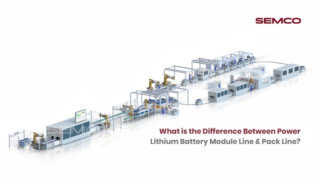
With the booming development of the new energy vehicle market, power lithium batteries are the core components, and their production line technology is also receiving increasing attention. In the production process of power lithium batteries, the module line and the Pack line are two indispensable key links. This article will deeply analyze the difference between the power lithium battery module line and the Pack line, in order to better understand and grasp the overall process of lithium battery production.
I. Power Lithium Battery Module Line: Integration and Management of Battery Cells
The power lithium battery module line is mainly responsible for combining and serializing single battery cells according to established specifications and parameters to form a battery module. In this process, the module line not only focuses on the physical combination of the cells but also attaches greater importance to performance matching and safety management between the cells.
Through precise process control, the module line ensures a high degree of consistency within each module and provides the necessary support, anchorage and protection in the structure to meet the requirements of the battery module in terms of mechanical strength, electrical performance, thermal performance and fault-handling capabilities.
In addition, the module line also integrates the battery management system (BMS) for real-time monitoring and management of the single cell. BMS can accurately detect the core voltage, internal resistance, capacity and other key parameters, and balance control through algorithms to ensure that the core in the module is always in the best working state. At the same time, BMS also has fault warning and protection functions, once found abnormal, can quickly cut off the circuit to prevent module safety accidents.

Process Flow of the Module Line
A standard prismatic LFP module line follows this sequence:
- Cell Incoming & Preparation
- OCV (Open Circuit Voltage) and IR (Internal Resistance) testing
- Barcode/QR code scanning and MES binding
- Automatic cell sorting and grading by voltage, capacity, and internal resistance
- Cell insulation film wrapping
- Cell cleaning and polarity inspection

2. Cell Stacking
- Automatic cell stacking and alignment (servo-controlled, ±0.1 mm precision)
- End plate loading and positioning
3. Module Compression & Banding
- Servo or hydraulic press compression to defined preload force
- Steel belt or tie rod installation to lock compression
4. Module Code Binding
- Laser marking of module QR code on end plate
- Cell-to-module data binding in MES for full traceability
5. Busbar & CCS Installation
- Cell Contact System (CCS) or individual busbar positioning
- Laser welding or ultrasonic welding of busbars to cell terminals

6. Weld Inspection
- CCD vision inspection of weld seam geometry
- Resistance measurement for conductivity validation
- Optional pull test for mechanical weld strength
7. Module BMS (Slave) Installation
- Voltage and temperature sensing harnesses connected
- Slave BMS or CMU (Cell Monitoring Unit) installed

8. Module End-of-Line (EOL) Testing
- Insulation resistance (IR) test
- Withstand voltage / Hi-Pot test
- Module terminal pole photography and dimensional check
- Electrical continuity verification
9. Module Offloading
- Completed modules transferred to buffer or directly to pack line
The entire module line is typically 95–100% automated in modern facilities, using fiber laser welding systems, vision alignment with ±0.1 mm accuracy, and torque-controlled compression.
Key Equipment on the Module Line
The module line is equipment-intensive and requires precision machinery:
- Cell sorting and grading machines — OCV/IR testers with auto-sorting conveyors
- Insulation film wrapping machines
- Robotic cell stacking systems — servo-driven pick-and-place with high-precision alignment
- Hydraulic/servo compression press — applies precise clamping force
- Steel banding machines — secure cell stacks with metal strips
- Laser marking machines — QR/barcode engraving on end plates
- CCS/busbar assembly stations — robotic positioning of copper or aluminum busbars
- Fiber laser welding machines — high-precision busbar-to-terminal welding
- CCD vision inspection systems — real-time weld quality assessment
- Module EOL test stations — insulation, continuity, Hi-Pot testing
II. Pack Line: Module Integration and System Construction
Unlike the module line, the main task of the Pack line is to integrate multiple battery modules through components such as connectors and wires to form a complete battery system. The Pack line not only focuses on the physical connection between modules, but also on the overall performance and safety of the battery system.
In the production process of the Pack line, the modules need to be accurately arranged and fixed to ensure that the connection between them is stable and reliable. At the same time, consideration needs to be given to the layout and optimization of the heat dissipation system to ensure that the battery system can work steadily in a high temperature environment. In addition, the Pack line also needs to configure suitable peripheral protection structures and electrical interfaces for the battery system to meet the needs of different application scenarios.

Process Flow of the Pack Line
A standard BESS pack assembly line follows this sequence:
- Pack Shell / Lower Case Loading
- Pack enclosure (aluminum or steel) loaded onto pallet conveyor
- Air tightness test of the empty lower case
2. Thermal Management Assembly
- Liquid cooling plate or thermal interface material (TIM) application
- Robotic glue dispensing with bead profile and volume monitoring
- Cooling plate leak test (if liquid cooling)

3. Module Installation
- Automatic or semi-automatic module insertion into pack enclosure
- Module positioning and mechanical fastening
4. Module Interconnection
- Inter-module busbars and HV cables installed
- Torque-controlled fastening for HV connectors
5. Master BMS Installation
- Main BMS/BMU mounted and wired
- Communication harnesses (CAN/RS485) connected
- BMS programmed and initialized via in-line BMS programming station
6. Contactor, Fuse & HV Connector Mounting
- Main contactors, pre-charge circuit, service disconnect installed
- HV connectors and LV signal connectors mounted
7. Pack Top Cover Installation
- Cover sealing (structural adhesive or gasket)
- Mechanical fastening

8. Complete Pack Air Tightness Test
- Pressure differential test to validate enclosure sealing integrity (IP rating compliance)
9. Pack End-of-Line (EOL) Testing
- Insulation resistance (Hi-Pot) — HV+ and HV− to chassis, typically up to 2500 VDC
- HV interlock function test
- BMS communication verification (CAN/RS485)
- Contactor operation test
- Charge/discharge functional test
- Thermistor and temperature sensor validation
- Final data upload to MES for full pack traceability

10. Pack Labeling & Packaging
- Compliance labeling (CE, UL, IS, etc.)
- Protective packaging for transport
Key Equipment on the Pack Line
The pack line integrates mechanical assembly with complex electrical and systems-level testing:
- Pack enclosure handling and conveyor systems
- Air tightness test machines (for empty enclosure and final sealed pack)
- Robotic glue dispensing systems — TIM or structural adhesive application
- Liquid cooling plate leak test benches
- Module insertion robots or guided assembly stations
- Automated busbar/cable assembly fixtures
- Torque-controlled nut runners — for HV connector fastening
- In-line BMS programming and communication test stations
- Hi-Pot and insulation resistance testers — up to 2500 VDC
- Pack-level charge/discharge cycling stations (for functional validation)
- MES data upload terminals — for full pack traceability and digital identity

III. Connection and Difference between Module Line and Pack Line
The module line and the Pack line are closely connected in the production process of power lithium batteries and together constitute a complete chain of lithium battery production. The module line is a key link in the transition from a cell to a battery system, and the pack line is the final step in integrating multiple modules into a complete system. The two have some differences in functionality, structure and requirements.
From a functional point of view, the module line is mainly responsible for the integration and management of the cells, ensuring that the cells within the module perform stable, safe and reliable. Pack Line focuses more on the overall performance and safety of the battery system, integrating multiple modules to form a complete battery system, providing a stable and reliable power solution for applications such as new energy vehicles.
From a structural point of view, the module line is relatively simple and is mainly concerned with the physical connection and performance matching between the cells. The Pack line is more complex, which needs to take into account the arrangement between the modules, the direction of the connection, the layout of the cooling system and many other aspects.
Conclusion
In summary, the power lithium battery module line and the Pack line have obvious differences in function, structure and requirements. Both play their respective roles in the production process of lithium batteries and jointly safeguard the performance and safety of litanium batteries. With the growth of the new energy automobile market, the technical requirements for power lithium battery module lines and Pack lines will continue to improve, which will promote the continuous innovation and development of related technologies.
Contact Semco Infratech to discuss your EV & BESS manufacturing requirements and discover how automatic assembly solutions can enhance your production efficiency, ensure product quality, and accelerate your path to market competitiveness.