

In the power battery pack of new energy vehicles, the core electrical integrated components of CCS constitute the “neural network” and “vascular system” of the battery management system (BMS).

What is CCS (Cells Contact System, Integrated Busbar)?
CCS, often referred to as Integrated Busbar or Wiring Harness Integrated Component in Chinese , is a highly integrated module that combines electrical connections, signal acquisition, and structural support within a battery module. Its core functions include:
- Series and parallel connection of battery cells : Multiple battery cells are connected in series or in parallel through copper or aluminum busbars to form a high-voltage electrical circuit.
- Signal acquisition : Accurately acquire the voltage and temperature signals of each battery cell and transmit them to the BMS for real-time monitoring.
- Overcurrent protection : Some designs integrate a fuse mechanism to cut off the circuit when the current is abnormal, ensuring safety.
- Structural support and insulation : I ts plastic structural components provide mechanical support and electrical insulation for the entire assembly.

Structural composition
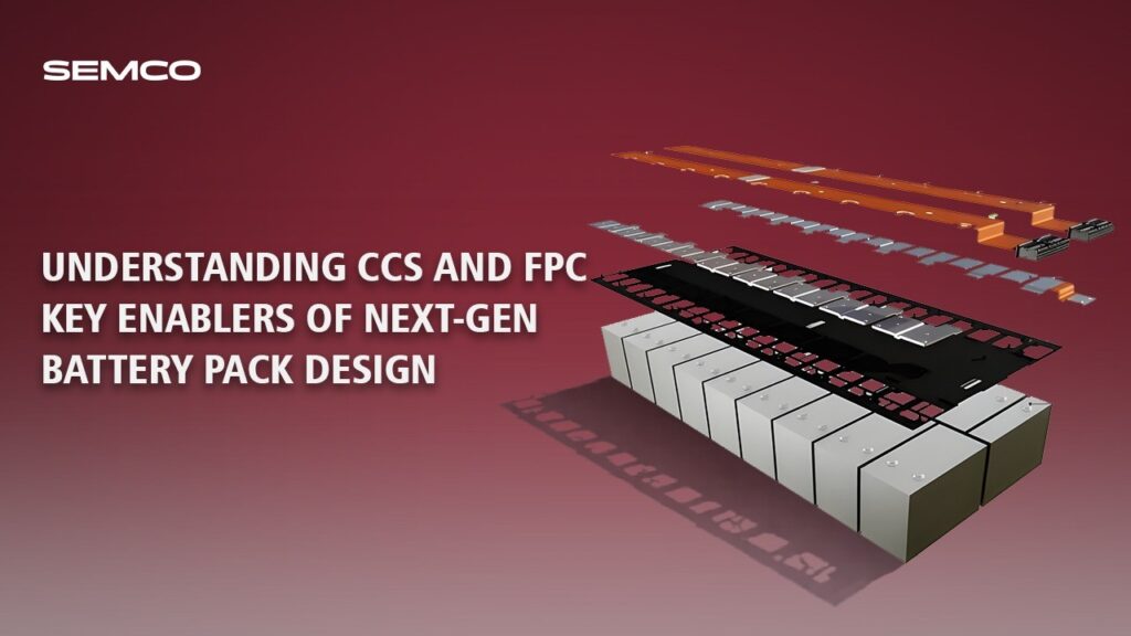
A typical CCS usually consists of three main parts: FPC, plastic support, and conductive busbar .
- Signal acquisition components include FPC (Flexible Printed Circuit), PCB (Rigid Printed Circuit), FFC (Flexible Flat Cable), or traditional wire harnesses. Currently, the mainstream solution is the FPC (Flexible Printed Circuit).
- Plastic structural components, such as injection molded brackets, bl ister packs, or PET hot-pressed films, serve to provide support, fixation, and insulation.
- Busbars: Copper or aluminum busbars, used to carry large currents.

Technical solutions and trends
Based on the different signal acquisition components, CCS can be mainly divided into the following categories, and their characteristics are compared as follows:

It started as a simple integration of wire harnesses:

Diagram of wire harness type: After the wire harness factory produces the integrated acquisition wire harness, it assembles the plastic bracket, aluminum busbar, and nickel terminals, and finally manually welds the aluminum busbar to the battery cell.
Gradually, it evolved into a series of new forms:

PCB board type: FR4 epoxy resin substrate is used to make rigid circuit boards through drilling, electroplating and other processes, integrating components such as nickel sheets and fuses.

FFC type: FFC refers to flexible flat cable, which is made of PET as base material, tinned copper wire and insulation layer pressed together, and realizes signal transmission through terminal connection.

Schematic diagram
A typical CCS structure diagram is shown below (descriptive illustration):
Top layer: It is an ultra-thin FPC (flexible printed circuit board) with precision sampling l ines etched on it and integrated temperature sensor (NTC) solder joints.
The middle layer is a plastic support (such as a vacuum forming board), on which the FPC is fixed by hot pressing or hot riveting. Positioning holes and slots are reserved on the support.

Flame-retardant plastic (such as PC+ABS, PA66) is melted and injected into the mold to form a tray with positioning holes, anti-slip texture and other structures, which is used to support battery cells, integrated signal acquisition components (such as FPC, wire harness) and copper and aluminum busbars.

The vacuum-formed partition board solution uses flame-retardant PC film to form a thin partition board through vacuum forming, which is then integrated with FPC, copper and aluminum busbars and other components through a hot riveting process.

The hot -pressing film solution typically uses PET insulating film (50-100μm thick) as the substrate, and uses a hot press to press the signal acquisition components (FPC/PCB), copper and aluminum busbars into one piece.
The copper-aluminum busbars are connected to the battery cell terminals via laser welding to achieve series and parallel connections. The sampling points on the FPC are connected to corresponding points on the copper-aluminum busbars via welding (such as ultrasonic welding) to collect voltage data.

FPC (Flexible Printed Circuit)
FPC plays the role of the “nerve” in CCS . It is a flexible circuit board made of polyimide (PI) or polyester film (PET) as a substrate, which directly replaces the traditional bulky sampling harness.
Core advantages
1. High density and integration: All voltage and temperature sampling l ines are integrated on a single thin film, el iminating a large number of separate wire harnesses and connectors, greatly reducing connection points and improving reliability.
2. Ultra-thin and lightweight: with a thickness of only 0.1 -0.3mm, it saves a lot of internal space in the battery pack and increases energy density.
3. Flexible and bendable: It can adapt to uneven cell surfaces or complex spatial layouts within modules, enhancing three-dimensional assembly capabilities.
4. Automation Adaptation: After CCS is integrated with FPC, it can be picked up and installed as a whole module by a robotic arm, which greatly improves the automation level of Pack assembly and production cycle.

Integration process in CCS
The integration of FPC and CCS is mainly accomplished through hot pressing or hot riveting processes:
- Hot pressing process : FPC, nickel sheet (if required), and conductor busbar are hot-pressed together into a single unit using a PET insulating film. This method offers the thinnest thickness (less than 1 mm) and the highest integration.
- Hot riveting process : The FPC and conductive busbar are fixed to the vacuum-formed or injection-molded plastic bracket using hot riveting posts. This method offers high structural strength and is a relatively mature technology.
The relationship between CCS and FPC and their significance for system design
Relationship: The FPC is the “brain” and “nerves” of the CCS, and the CCS is a “functional module” integrated with the FPC as its core. You can understand it as: CCS = FPC (signal acquisition and transmission) + structural components (support and insulation) + copper and aluminum busbars (power transmission).
Significance for battery pack system and structural engineers:
- Improving space utilization: The thin and light characteristics of CCS (especially FPC solutions) free up valuable space inside the battery pack, which is key to improving volumetric energy density.
- Simplified design and assembly: High integration reduces the number of parts, simplifies BMS wiring, reduces design complexity, and promotes production l ine automation.

- Enhanced reliability: Fewer wiring harness connection points reduce the risk of failure due to poor contact or wear, resulting in more stable sampling signals.
- Supporting new processes and cost reduction: Understanding the advantages and disadvantages of FPC, FDC, FFC and other solutions helps to balance performance, cost and processability. For example, in the field of energy storage, the more cost-effective FDC solution can be considered.
CCS (Computer-Oriented System) is the physical carrier for the electrical integration of the battery pack, while FPC (Flexible Printed Circuit) is the core technology path for achieving intelligent and lightweight data acquisition. Mastering the design selection, process matching, and reliability verification of both is an essential skill for modern battery pack system and structure engineers.

Contact Semco Infratech to discuss your BESS manufacturing requirements and discover how automatic assembly solutions can enhance your production efficiency, ensure product quality, and accelerate your path to market competitiveness.