

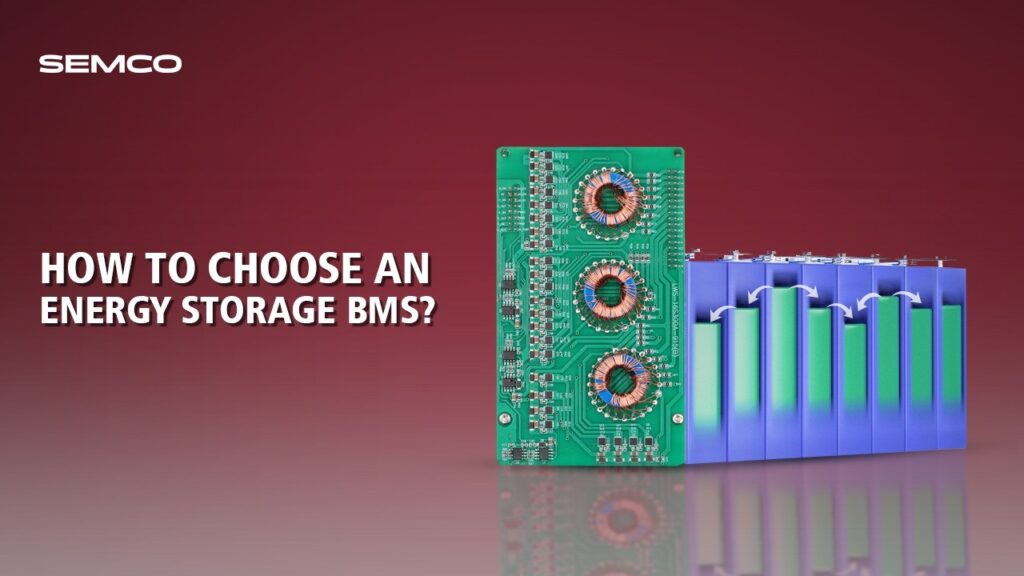
A Battery Management System (BMS) is the intelligence layer of any Battery Energy Storage System (BESS) — it monitors, protects, and optimises the battery pack across its entire lifecycle. As the global energy storage market is projected to reach approximately 1,100 GWh by 2040, selecting the right BMS has become one of the most critical technical and commercial decisions for project developers, integrators, and operators.

First, Consider the Hardware.
It needs to accurately assess the battery status and execute commands. It must collect the voltage and temperature of each cell and the current of the entire battery pack. Accurate voltage measurement is crucial; otherwise, the calculated remaining capacity will be significantly off.
A dedicated chip is typically used, with an accuracy controlled within ±2mV. Temperature must be measured directly on the cells, especially the sides and tabs, as these areas best reflect the battery’s condition. Measurements should be taken in temperatures ranging from tens of degrees below zero in winter to tens of degrees Celsius in summer.

Current selection depends on power. For low-power energy storage (e.g., a 5kWh home battery), a shunt is sufficient and inexpensive. For high power storage (e.g., several hundred kW grid-side storage), a Hall effect sensor is necessary due to its strong anti-interference capabilities and accuracy.
For large-scale BESS, prioritise BMS platforms with EKF-based or ML-augmented SOC/SOH engines, as conventional methods struggle with the nonlinear degradation of lithium cells at scale. Top-tier BMS units achieve voltage detection within ±0.2% accuracy and can trigger safety shutdowns in under 500 milliseconds, which reduces fire and cascade failure risks by up to 68%.

The execution section mainly involves switching and balancing:
for charging and discharging circuits, relays are used for low-power circuits, while contactors with arc suppression are required for high-power circuits, otherwise they are prone to burning out when disconnected; the balancing function also varies depending on the situation.
Small residential energy storage uses “passive balancing,” which involves connecting a small resistor to the higher voltage battery for discharge, which is low-cost; for high-power applications such as grid-side and industrial/commercial systems, “active balancing” must be used, which uses inductors or capacitors to transfer the charge from the higher-voltage battery to the lower-voltage battery, otherwise, hundreds of cells will be inconsistent, and some will fail after two years, resulting in wasted money.

In addition, hardware protection must be adequate. Outdoor BMSs need to be protected against rain and dust, and the casing should be IP65 rated; factory BMSs need to be protected against oil stains, and the circuit boards should be coated with conformal coating. If these details are not done well, there will be many failures later.
Assess BMS Architecture — Centralised, Distributed, or Modular
Three primary BMS architectures exist, each suited to different project scales and complexity:

For utility-scale and commercial & industrial (C&I) deployments, the three-tier hierarchical distributed architecture (BMU → Rack BMS → Master BMS) is the industry standard. It enables efficient fault isolation, granular cell-level monitoring, and the scalability needed for multi-rack configurations.
Then comes the Software part,
which is like the “brain” of the BMS. The core is accurate calculation and correct judgment. The most crucial part is calculating the remaining capacity (SOC) and battery health (SOH): SOC cannot just calculate how much it has been charged and discharged. It needs to be calibrated regularly. For example, measure the open circuit voltage once a day when the battery is not in use in the early morning to correct previous errors.

Otherwise, if the user sees an SOC of 50% but there is actually only 30% left, they will be at a loss when there is a power outage. SOH is to see how much longer the battery can be used. For example, if a new battery can store 100Ah, but after a year it only has 90Ah left, the SOH is 90%. It also needs to be combined with the number of cycles and internal resistance. If the internal resistance increases, it means that the battery is aging.
Safety protection also relies on software. It shouldn’t shut down at the slightest problem; it needs to be tiered. For example, with lithium iron phosphate batteries, an alarm should sound when the voltage reaches 3.6V to alert the user; at 3.65V, the PCS should reduce power by half to prevent further rapid charging; and at 3.7V, it should completely shut down. This approach is safe and doesn’t disrupt normal power supply. Temperature control works similarly: at 45℃, the cooling fan should be on; at 50℃, power should be reduced; and at 55℃, it should shut down to avoid damage from sudden power outages.
Communication Protocols and System Integration
There’s also the communication part. The BMS can’t operate alone; it needs to connect with other devices. It uses a CAN bus with the battery acquisition module for fast data transmission and interference resistance. It needs to be able to send signals to the PCS, for example, the BMS can tell the PCS, “The battery only has 15% charge left, stop discharging,” and the PCS must obey. It also needs to connect with the EMS (Energy Management System), as the grid side energy storage needs to transmit data to the dispatch center in real time. When the dispatch center orders discharge, the BMS must respond within one second without delay.
A BMS does not operate in isolation — it must integrate seamlessly with the PCS, EMS, SCADA, and potentially cloud platforms. Communication protocol selection is therefore a crucial part of BMS evaluation:

CAN Bus remains the undisputed standard for internal BMS communication due to its deterministic message prioritisation — critical safety messages such as overvoltage trips take precedence over routine telemetry. Ethernet handles high-bandwidth cloud and utility integration. A BMS architecture that uses RS485 for cell-level monitoring in utility-scale projects risks latency-induced instability.
Ensure the BMS can communicate with your specific inverter or PCS using confirmed, documented protocol compatibility — especially important for closed-loop control where the inverter reads real-time SOC and adjusts charging behaviour accordingly.
Finally, the solution must be adjusted according to the specific scenario; a one-size-fits-all approach is not feasible.
For residential energy storage, the BMS needs to be inexpensive and simple, with hardware integrated onto a single board, small enough to fit in a balcony cabinet. The app should only display key information such as SOC and remaining time, making it easy for users to understand.
For industrial and commercial applications, it must balance peak-valley arbitrage and backup power, for example, being able to link with diesel generators to automatically start the generator when the stored energy is insufficient. It also needs to support rapid grid-connected/off-grid switching to ensure that critical factory equipment is not interrupted during power outages. The grid side has the highest requirements: hardware must have dual backups (e.g., if the main controller fails, the backup immediately takes over), response must be fast, communication latency with dispatching cannot exceed 1 second, and it must pass various certifications from the State Grid; otherwise, grid connection will be denied.

When implementing the system, compatibility must be considered. The BMS must match the protocols of the battery and PCS.
For example, CATL’s batteries use one protocol, while Sungrow’s PCS uses another. The BMS must support both, otherwise it cannot be connected. Maintenance must also be convenient, allowing remote detection of fault locations (e.g., “abnormal voltage in battery cluster No. 3”), eliminating the need for personnel to search on-site. Compliance is also essential. Domestic certification requires CQC certification, while export certification requires UL or CE; otherwise, the project will not pass acceptance.
Conclusion
In summary, this solution revolves around “battery safety, durability, and scenario compatibility.” It doesn’t need fancy features; it just needs to solve practical problems and be implemented smoothly.
Selecting the right BMS for an energy storage system is a multi-dimensional decision that directly determines the safety, performance, lifespan, and return on investment of the entire BESS asset.

Contact Semco Infratech to discuss your BESS manufacturing requirements and discover how automatic assembly solutions can enhance your production efficiency, ensure product quality, and accelerate your path to market competitiveness.
For demos, solutions, or collaborations:
Connect at sales@semcoindia.com | +91-8920681227 | www.semcoinfratech.com
__________________________________________________________________________________