

Whether used in new energy vehicles or energy storage scenarios, the core function of a battery pack is to store energy . If we compare a battery pack to soldiers in an army, then an energy storage container can be seen as a well equipped.
Energy storage containers have a complex structure, mainly consisting of the following key components: container, battery pack, electrical system, fire protection system, communication and monitoring system, thermal management system, and auxiliary systems (air conditioning, lighting, etc.).
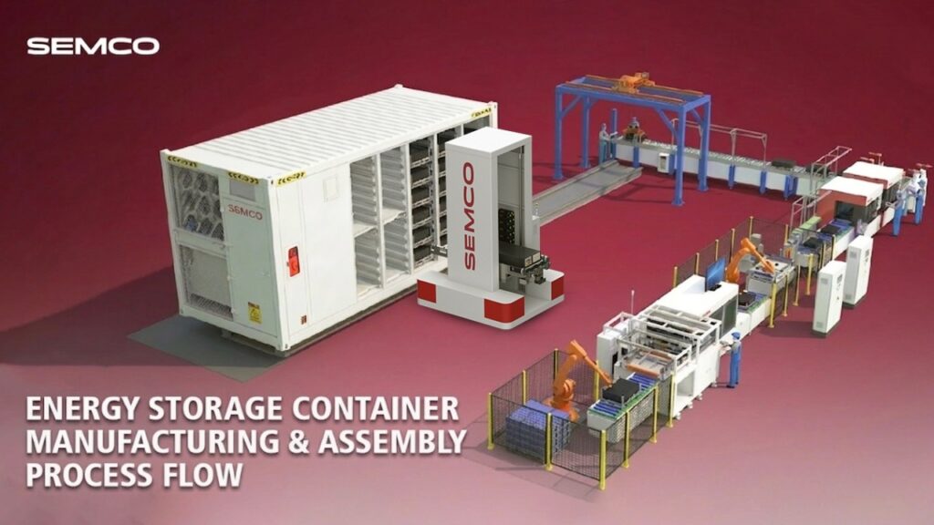
Semco Infratech delivers complete turnkey Cell-to-Container solutions for grid-scale BESS, enabling developers, EPCs, utilities, and manufacturers to deploy reliable, scalable, and bankable energy storage infrastructure.

This issue will provide a detailed introduction to the structure and manufacturing process of energy storage containers.

Battery compartment launched
After the battery compartment is installed, its appearance, dimensions, and protection level generally need to be inspected according to the design drawings to ensure that the compartment’s strength, corrosion resistance, and sealing meet product quality requirements . Currently, the container specifications used for large-capacity storage products are generally 20 feet and 40 feet; the specific external dimensions can be found in the table below.

Battery racks are used to mount and secure battery packs, and are generally made of welded steel. Battery racks need to meet high strength requirements; a single 1P104S battery pack can weigh over 600 kg. To increase energy density, a single row of battery racks often needs to hold nearly 10 battery packs.
Fire Protection System Installation
Compared to power battery packs, energy storage battery packs have higher requirements for safety performance, so fire protection systems are added to ensure their safety during service.
Fire protection system: Smoke sensors, temperature sensors, fire extinguishing devices, etc. When an abnormal situation such as a fire is detected, the fire extinguishing device can be automatically activated to carry out fire extinguishing operations, prevent the fire from spreading, and ensure the safe operation of the energy storage system.
Currently, most fire protection systems in the industry adopt a three-level fire protection design to achieve ” prevention and firefighting combined, with multiple layers of protection “.

Main reference standards:
GB51048-2014 Design Code for Electrochemical Energy Storage Power Stations
T/CEC373-2020 Technical Specification for Fire Protection of Prefabricated Lithium Iron Phosphate Battery Energy Storage Power Stations
The installation of fire protection systems mainly includes: PACK-grade submerged piping, solenoid valves (puncture valves), audible and visual alarms, perfluorohexanone (or heptafluoropropane), fire sprinkler systems, etc.

Thermal Management System Installation
The first generation of large energy storage products were mostly air-cooled energy storage containers (walk-in type, meaning maintenance personnel can enter the cabin for inspection). The advantages of air-cooling are simple structure, easy installation and low cost, but the cooling efficiency is not high and it is difficult to meet the heat dissipation requirements of energy storage systems.

Most second-generation large-capacity energy storage products are now equipped with liquid cooling systems , which not only improves the heat dissipation efficiency of the battery pack and the temperature consistency of the cells, but also greatly increases the energy density of the products.
The liquid cooling system mainly includes: a liquid chiller, liquid cooling pipes, valves, and liquid cooling plates (integrated into the battery pack housing).
Installation process: Generally, the liquid cooler and main liquid cooler pipe are installed first, followed by the installation of secondary and tertiary pipes. After the pipe installation is completed, an airtightness test (<150Pa) is performed. After the entire battery compartment is integrated, coolant needs to be added.
This also includes the installation of air conditioning and ventilation fans (to improve the efficiency of the liquid cooling system and reduce the probability of internal condensation).

Electrical System Installation
The electrical system architecture of battery energy storage products is shown in the figure below, which is generally divided into main circuit and control circuit.
Main circuit: Includes DC circuit, PCS, and AC grid connection interface. The DC side typically runs from the battery cluster to the high-voltage box, and then to the combiner cabinet, directly connected by DC cables, and equipped with necessary protection and switching devices. The battery compartment and electrical compartment are isolated by a steel fireproof door.
With the increasing capacity of battery compartments, PCS is generally arranged separately or integrated with other equipment such as transformers and switchgear in a prefabricated compartment.
Control circuit: mainly supplies power to the equipment inside the cabin. Generally, BMS, local controllers, fire protection systems, etc. need to be powered by UPS (uninterruptible power supply) to ensure normal function in case of unexpected failure.

Installation process flow:
- Wiring harness from battery cluster to high-voltage box
- Cable harness installation from high-voltage box to combiner cabinet
- Combiner cabinet installation
- Installation of BMS display screen, emergency stop switch, indicator lights, etc.
- Transformer installation
- Electrical system wiring installation and junction box wiring connection
Battery System Installation
Battery pack insertion: This is typically done by inserting the battery packs into the racks using a forklift. Due to the very limited space, this task is usually only achievable by skilled workers. In the future, as the automation of energy storage container assembly processes matures, this task may be replaced by automated equipment.

Installation process flow:
- Battery pack entry compartment
- High-voltage box installation
- Battery pack connection
- Installation and connection of secondary and tertiary liquid cooling pipes
- PACK Submersible Water Fire Protection Piping Connection
- Solenoid valve wiring harness connection
Electrical Performance Test
Pre-power-on checks:
1. Grounding reliability testing: Use a grounding resistance tester to check the grounding reliability of the battery pack, high-voltage box, and battery clusters. Generally, apply a 10A current, and the grounding resistance value should be ≤0.1Ω.
2. Insulation testing: Ensure the battery cluster is connected to an external power source or other electrical equipment. Using an insulation resistance tester, connect the positive and negative terminals and measure the insulation resistance of the battery cluster to ground. A value of ≥20 MΩ is generally required.

Power frequency withstand voltage: Short-circuit all circuit ports and apply the corresponding test voltage to ground (the enclosure). The system should exhibit no breakdown or arcing. The test voltage value should conform to the requirements of GB 7251.1-2005.
Impulse voltage: The minimum rated cumulative withstand voltage of low voltage switchgear and circuits inside the container shall at least comply with the values given for Class IV overvoltages in Table 1 of GB/T 16935.1-2008.
Charge and discharge test: Generally, the two compartments are towed together . The test requires that the dynamic voltage difference during charge and discharge be less than a certain value, the maximum temperature be less than 40℃, the temperature difference be less than 5℃, the temperature rise of the plug surface be less than 50℃, the discharge energy be greater than the rated energy value , and finally the SOC needs to be adjusted to the factory setting value (usually 50%).

Lifetime Test
Rain Test: Conduct a rain test on the entire cabin using equipment for no less than 3 minutes, requiring that the cabin does not leak.
Label and marking inspection: Inspect the battery compartment serial number, nameplate, warning signs, logo, grounding markings, fire safety markings, polarity markings, etc., to ensure they are clear, accurate, traceable, and conform to the drawings and specifications.
Product appearance inspection: Ensure the battery pack is free from deformation or cracks, and the exterior is free of dirt; the coating color of the casing is consistent, with no blistering or peeling; the grounding structure is securely fixed; and the main valve is closed after draining the liquid cooling pipes.
Know More About Semco Infratech’s BESS Assembly Solutions
Explore how Semco Infratech’s automatic BESS assembly lines can transform your battery manufacturing operations. The company offers comprehensive solutions tailored to your production scale—from startup R&D operations to full commercial manufacturing volumes. Semco’s integrated approach combines state-of-the-art equipment, intelligent process management, and expert technical support to establish efficient, scalable battery production capabilities.

Contact Semco Infratech to discuss your BESS manufacturing requirements and discover how automatic assembly solutions can enhance your production efficiency, ensure product quality, and accelerate your path to market competitiveness.